

1. Introduction
The promotion of pulp properties to obtain the desired quality for formed paper is basically carried out through a mechanical treatment on fibers called refining which produces external and internal fibrillation of fibers, fiber cutting and the fines in pulp.1) Disc refiner is a widely used device in pulp refining due to the flexibility of plate design and relatively simple structure. And the refining plate is the main part of the disc refiner, which is the component that directly applied complex forces and energy on fibers and improve the flexibility of fibers and fiber bonding area. It’s very important to design an optimal plate with a reasonable selection of bar width, groove width, bar angle and dams, which can make a better pulp quality and lower energy consumption during refining.
Many plates are involved in pulp refiners, broadly speaking, there are two main types of plates, ones with straight bars and ones with curved bars. Currently, the straight bar plates are the most widely used refining plates, while the attack angle interlaced by bars of stator and rotor varies during refining which induces a less uniform pulp and fiber quality through theoretical analysis. However, refining with a curved bar plate can make a less change in attack angle2,3) and lower fiber cutting rate which can effectively retain fiber length.4-6) In previous study, very little research about the design and characterization of curved bar plated was conducted even though there are some advantages of it compared to straight bar plate, meaning more studies should be carried out on that in the future.
Nowadays, the design of refining plate is usually based on the refining intensity, such as specific edge load (SEL), specific surface load (SSL), C-factor theory et al.,7-9) and fluid mechanics of pulp in refining zone. SEL is widely used in plate design and actual refining because of its simplicity and easily obtained of all factors,10) in which the bar profile is connected to refining intensity by considering the length of the bar edges. And the approximately value of SEL was selected by experienced papermakers when refining certain pulp at a given consistency. However, it fails to consider many important factors having influence on refining result, such as pulp consistency, bar width, and gap clearance.And many refining intensities, reference specific edge load, SSL, modified SEL et al.,11-13) modified from SEL are proposed by considering more factors influencing the refining performance. As a representative of SEL-based refining intensities, SSL accounts for energy expenditure over bar width by extending the SEL theory with bar width included and is a good indicator for measuring the change of freeness and fiber average length,14) which would be a potential theoretical base in the refining plate design.
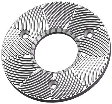
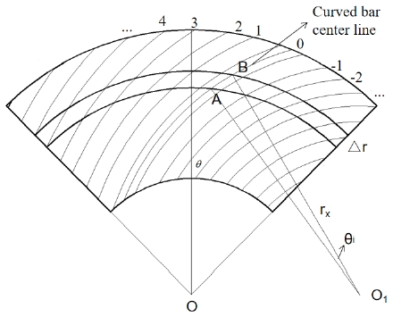
Isometric curved bar plate was been proposed by Liu et al.15) for pulp refining, as shown in Fig. 1, in which the bar width and groove width are constant from inter to outer part of the refining zone. Two main parameters of curved bar design, starting point of center curved bar central curve and curved bar angle, which have a great influence on the curved bar curve were put forward in this study. The characterization parameters of SEL and SSL of isometric curved bar plate were calculated aiming to a better measure of it. At last, the relation between two characterization parameters and two main design parameters of curved bar plate were analyzed, meanwhile, the refining performance of different isometric curved bar plates with different starting points and bar angle were further explored by the analysis of SEL and SSL.
2. Design of Curved Bar Plate
2.1 Definition of curved bar angle
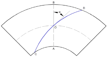
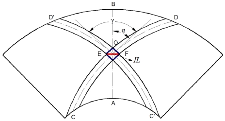
No clear definition of curved bar angle was proposed in previous study. Two patents invented by Leider et al.16) and Hackl et al.17) measure the curved bar by two different methods and the detailed information can be found in reference 15. Only one bar edge of curved bar was defined by above two methods which can’t represent the full arc of the curved bar. Therefore, a new definition of bar angle for it was proposed by defining a central curve of curved bar plate, as shown in Fig. 2. The curve that passes through the intersection point O of the segment center line and the center circle of plate, is called the curved-bar plate center curve, and the angles α, which is denoted by the angle between the tangent of the central curve at point O and segment center line AB, is the bar angle bar curved bar plate.
2.2 Two parameters of curved bar design
As depicted in Fig. 2, the curved bar center curve can be determined by the point C, which is appointed as the starting point of central curve of curved bar plate, and the bar angle α measuring the average radian of the curved bar. And the bar shape will be changed as soon as any change in any parameter of the two parameters mentioned above. The details of these two parameters will be discussed in the following.
2.2.1 Starting point of curved bar plate central curve
The average radian of the curved bar is determined by the location of the starting point of curved bar plate central curve when the bar angle keep constant, as shown in Fig. 3. The location of starting point Cn can be described by two factors, one is the radius and another is the angle βn that between the O1Cn and the central line of the segment, so the starting point of central curve CnDn can be represented by (βn,Rn). Especially, the second term of starting point is constant when it is on the inter-circle line of the segment and equals to inter radius Ri. Meanwhile, the first one is fixed, that equals to the half of the segment center angle, when it is on the left or right edge of the segment.
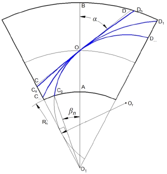
The starting point Cn is not arbitrary location of the boundary of refining zone, but there is a certain range limit for its location. As shown in Fig. 3, the right limit starting point is C0, which is the intersection point of the center circle, that is tangent to left edge of the segment, of center curved bar and the inter-circle of plate. And the left limit starting point is infinitely close to point C, but cannot coincide with C. So the proper location of starting point can be chosen in this range for specific needs with the fixed bar angle of curved bar plate.
2.2.2 Bar angle of curved bar plate
Bar angle is one of the important factors for the design of curved bar plate, and its influence on curved bar should be explored when fix the starting point C of curved bar plate central curve. It can be concluded from Fig. 4, there is a great impact of the bar angle on the curve of the curved bar.
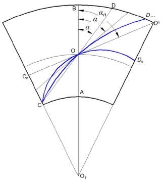
The curve of curved bar varies with the change of bar angle, but there is a limit of it like the location of starting point which must be declared. The minimum bar angle limit is α, between the center line of segment and the line connected by the starting point C and O. However, the minimum bar angle α is a limit value that impossible to reach in actual design due to a circle can not tangent to one line and pass another point of the same circle. Meanwhile, the maximum value of bar angle can be defined as αn, the angle between the center line of segment and the line OCn, however, the proper the maximum limit angle could be selected in design of an actual curved bar plate with specific requirements, which can not exceed the range of α~αn.
2.2.3 Bar edges of curved bar
The central curve of segment center bar can be represented as Eq. 1, through the analysis of starting point of curved bar plate central curve, Cn and bar angle of it.
When the central curve of segment center bar was fixed, the central curve can be defined in polar form, as shown in Eq. 2,
Where the ρ is the polar path (mm) and r0 is the radius of central curve (mm).
As shown in Fig. 5, if the groove width of the isometric curved-bar plate is g, the bar width is b, and the point O1 is defined as pole, the equation of the center bar edges is
where the right arc of the center bar is obtained by subtraction and left one is obtained by addition.
and the functions of the 2nth bar edges, when n≥1, on both sides of the center curved bar can be expressed as
Similarly, the equations of the (2n+1)th bar edges, when n≥1, can be determined by Eq. 5.
3. Characterization of Isometric Curved Bar Based on SEL and SSL
3.1 SEL of the isometric curved bar plate
The SEL is a common way of quantifying refining intensity,8) which denotes the net energy applied to each meter of the bar crossing (J/m) and is calculated by Eq. 6.
where Pnet is the net refining power (kW), n is the rotation speed (r/min), and BEL is the total bar edge length the fibers will experience during the intersection of the opposite bars per revolution (km/rev), sometimes referred to as the cutting edge length (CEL), which is the characterization parameter of SEL, and the standardized measure in the industry was provided by TAPPI standard TIP 0508-05 (1994),19) as shown in Eq. 7,
where r1 is the inner radius of the plate (mm), r2 is the outer radius of the plate (mm), nr is the total bar number of the rotor, ns is the total bar number of the stator, and α is the bar angle of the plate (°).
The BEL is proposed for straight-bar plates at first, and it cannot be directly applied to curved-bar plates. So the calculation of the CEL of curved-bar plates should be further developed.
The principle of calculating BEL of curved-bar plates is similar to that of the straight bar, as shown in Fig. 5, the bar segments are divided into several zones and the number and length of the bars in each zone is counted. And the bar edge is represented by the center line of each curved bar, so the CEL of the curved-bar plate is calculated by Eq. 8.
where θi is the center angle of the curved-bar center line at zone i, rx is the circle radius of the curved bar center line, nri is the total bar number of a rotor at zone i and nri is the total bar number of a stator at zone i.
The circle radius rx of curved bar center line on the plates can be expressed by Eq. 9, according to the design method of curved bar plate mentioned earlier.15)
Where r0 is the radius central bar center line of the plate (mm), n is bar number as a base of central bar which is indicated in Fig. 5.
3.2 SSL of the isometric curved bar plate
Specific surface load (SSL) was introduced by Lumiainen8,18) with the hypothesis of that the energy is transferred to the fibre bundles also in edge-to-surface contact as well as in edge-to-edge contact, which accounts for energy expenditure over bar width and is an extension of the SEL theory with the bar width included. It is obtained by dividing the old specific edge load, SEL, by the bar width factor impact length (IL), as shown in Eq. 10.
The length of the refining impact across the bars of straight bar plates depends on the width and the attack angle of the bars, and the impact lengths can be explained by Eq. 11.
Where bs and br are the bar width of stator and rotor, and γ is the attack angle of the rotor and stator bars.
Similar to the calculation of IL of straight bar plate, as shown in Fig. 6, the IL of curved bar plate can be calculated by Eq. 12, considering the attack angle γ.
According the definition of characterization parameter of refining intensity, the characterization parameter of the SSL of isometric curved bar plate is
The SSL theory has partly replaced the SEL theory and it seems to work quite well when bars are so narrow that fiber flocs when receiving a refining impact cover the whole width of bar surface. So it must be considered that the refining characteristic depends both on the SSL and bar width. It was cited that SSL works quite well with coarse fillings when bars are wider than the length of the fiber flocs. Heavily fiber cutting will occurs when the bar width is much narrower. Both of SEL and SSL still have many weak points, but these two theories offer very practical tools when selecting fillings and characterizing the refining process.
In this paper, a type of isometric curved bar plate for hardwood pulp refining was analyzed and the characterization parameters of SEL and SSL curved bar plate with different starting points and bar angles was explored. At last, the refining performance of these plates were estimated by the characterization parameters of SEL and SSL.
4. Results and Discussion
4.1 Parameters of the isometric curved bar plate
The common parameter of isometric curved bar plates analyze in this study is shown in Table 1, and it was explored in two aspects.
Table 1.
The primary bar parameters of isometric curved bar plates
| Bar width | Groove width | Bar height | Inner diameter | Outer diameter | Center angle | Number of bars |
|---|---|---|---|---|---|---|
| 2 mm | 3 mm | 4 mm | 120 mm | 300 mm | 40° | 171 |
First, the curved bar plates were designed with different starting point. Through the analysis of the bar structure of the curved bar plates, the starting points were designed as (20°, 80), (20°, 75), (20°, 70), (20°, 65), (20°, 60), (19°, 60), (18°, 60) and (17.13°, 60) with a constant bar angle of 42°, which were not exceed the range defined above. And the second aspect, that the plates with varying bar angle were analyzed. Bar angle of different curved bar plates were selected, such as 28°, 32°, 35°, 39°, 42°, 45°, 48°, 51° and 54°, but the same starting point (20°, 66). And the isometric curved bar segment designed with different bar angles and starting points mentioned above can be seen in Table 2.


4.2 The curved bar angle and characterization parameters of SEL and SSL
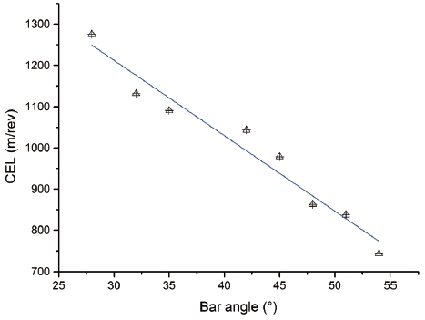
The bar angle of central curve affects the curve of refining plates under the same starting point, so its effects on the characterization parameters of SEL and SSL, such as CEL, IL and CEL·IL were analyzed. As shown in Fig. 7, the CEL is the characterization parameter of SEL which is the widely used refining intensity in the mill and it linearly decreases as the bar angle increases, which means that the CEL of curved bar plate is larger when the bar angle is small under the same starting point of central curve. And the refining intensity, SEL, would be moderate for the curved bar plates with small bar angle under the same refining process which is suitable for low intensity refining, such as hardwood pulp or waste pulp refining.
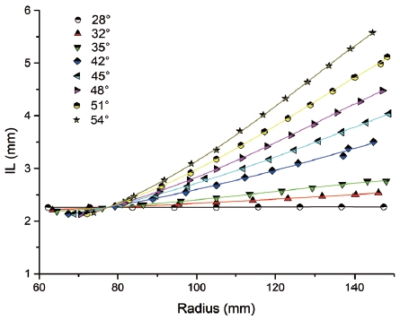
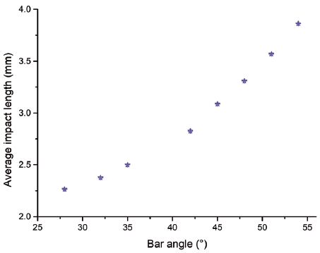
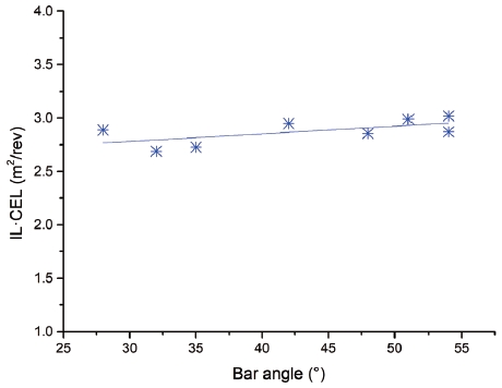
The impact length of curved bar plates with the same starting point over radius, the average impact length and the characterization parameter of SSL were analyzed, as shown in Figs. 8, 9 and 10. It was found that the impact length gradually increases as the radius of rotor and stator bars interaction increases, and the rate of the IL increasing of curved bar plate with larger bar angle is higher than that of smaller one. However, as a special case, the IL of curved bar plate with the bar angle of 28° over radius keep constant due to its bar shape is similar to the straight bar plate with the bar angle of 28°. It can be concluded that the bar interaction length increases over radius and the value of it is large for the curved bar plate with large bar angle which would effect the bar force along radius and the uniformity of the refining process that need to be further studied. The IL change of different curved bar plates with different bar angle over radius effect the average impact length, as shown in Fig. 9. The average impact length of curved bar plates with same starting point gradually increases as the bar angle increases, and the CEL·IL was calculated through the average impact length. As the bar angle of the curved bar plate increases, it remains almost unchanged, which means a constant SSL of curved bar plates with different bar angle under the same refining process. Actually, the refining results would be different when the pulp is refined by curved bar plates with different bar angles and the refining intensities of them were different, so the it would be invalid to measure the refining process with SSL when the curved bar plates with different bar angles were used.
4.3 The starting point of central curve and characterization parameters of SEL and SSL
Like the bar angle of central curve, the starting point of it affects the curve of refining plates, the characterization parameters of SEL and SSL, such as CEL, IL and CEL·IL also need to be analyzed. As shown in Fig. 11, the CEL is the characterization parameter of SEL slightly reduces which can be viewed as constant as the starting point of central curve gradually close to the point C, which means a almost unchanged SEL when refining with curved bar plates with different starting point of central curve. So it is useless of SEL when characterizing the refining process refined by curved bar plate with different starting point.
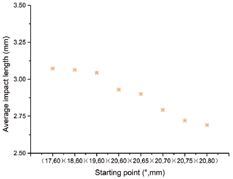
The impact length of curved bar plates with the different starting point over radius, the average impact length and the characterization parameter of SSL were analyzed. As shown in Fig. 12, the change of impact length over radius of curved bar plates with different starting points is same to that of curved bar plates with different bar angles, which means the IL over radius increases with radius and the changing rate is larger for the plate with starting points and the value of it is large for the curved bar plate with a starting point away from point C. As a special case, the IL of curved bar plate with the starting point of (20°, 80) over radius keep constant due to its bar shape is similar to the straight bar plate with the bar angle of 42°. However, the impact length of different curved bar plates at the radius of 108 mm are the same due to all plates are with the same bar angle, which can be seen as a critical radius. The IL of refining plates with starting point close to point C when the radius is less than 108 mm, and then the IL changing is opposite when the radius is larger than 108 mm.
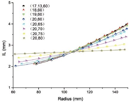
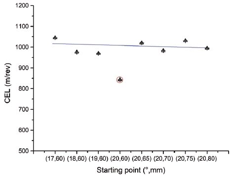
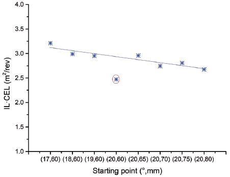
It is worth noting that the IL change of curved bar plates over radius is almost identical when the starting point is gradually closed to the right limit point C0 and there would be a critical starting point that the IL of refining plate over radius is not changing, which can be effectively explained by average impact length, as shown in Fig. 13. The IL of curved bar plates over radius keep constant when the starting point is away from point (19°, 60) on the side close to C0, so the critical starting point can be seen as (19°, 60). And the average impact length of curved bar plates gradually reduce when the starting point is away from critical starting point on the side closed to C. So it is no doubt that there is a slightly decrease of CEL·IL of curved bar plates when the starting point is closed to point C of Fig. 4 due to the constant CEL and decreasing average impact length. It can be concluded there are less change of CEL and CEL·IL of curved bar plates with different starting points, as shown in Fig. 14. Meanwhile, there is a sudden drop of the CEL and of curved bar plate with starting point of (20°, 60) which is a special point formed by the intersection of light edge and inner edge of segment.
5. Conclusions
(1) Two important parameters, the starting point (βn,Rn) and the bar angle of central curve α, of curved bar plate design were proposed, and the central curve of isometric curved bar plate can be determined by the two parameters mentioned above. Meanwhile, the isometric curved bar plate can be designed through two methods, one designed with fixed starting point of central curve and various bar angle and another with constant bar angle of central curve and various starting points.
(2) The function of curved bar edges can be determined by the bar width, groove width and the radius of central curve of center curved bar. To better characterizing the refining performance of different curved bar plates, the refining intensities, SEL and SSL, and the characterization parameters of them, CEL and CEL·IL were calculated.
(3) The change of characterization parameters of SEL and SSL were analyzed over different starting point of center bar and the bar angle. CEL of the isometric curved bar plates with same starting point and different angle gradually decreases with the increasing of bar angle, however, the CEL·IL is almost unchanged. Meanwhile, the characterization parameters of SEL and SSL change little or keep constant, which means the preferable design method of isometric curved bar plate is with fixed starting point and various bar angle and it would be useful measure the curved bar plates using SEL.
