

1. Introduction
Papermaking is a complex and sophisticated manufacturing process. Keeping sheet quality uniform across the entire basis weight range is a great challenge. The quality of the manufactured paper is evaluated in two dimensions: one is the average sheet property profile along the sheet moving direction while it is being manufactured, which is referred to as machine directional (MD) control, and the other is the sheet profile across the width of the paper machine, which is referred to as cross-directional (CD) control.1) For any paper machine, the sheet properties must be continuously monitored and controlled to guarantee that the product quality specifications are satisfied along both the MD and CD.2,3) It is generally recognized that the CD control problem in web forming processes is much more challenging than the MD control problem. This is due to several difficulties including the high dimensionality of the cross-directional system, the high cross-directional spatial coupling among actuators, the uncertainty in the model, and the limited control freedom of the actuators.4,5) The CD basis weight profile is a very important quality measurement of paper in the papermaking process. The objective of the CD control system is aimed at reducing the CD variation of the paper web as it is being made.
The CD profile variations are generally found to occur at a much slower pace than the MD variations. The CD profile variations can be traced to flow patterns inside the headbox. The modern hydraulic headbox is equipped with dilution valves for basis weight profile control. In the hydraulic headbox with dilution actuators, the full-width CD basis weight is adjusted by injecting dilution water upstream of the homogenizer.6) The task of the dilution valves is to mix the dilution water as evenly as possible into the stock that flows from the inlet header, which creates a stock flow whose consistency differs from that of the inlet header flow.7) The dilution valves are connected to electric actuators that are controlled by the dilution profile control system. The control system is used to regulate the local stock consistency to effect weight profile changes. This approach replaces the traditional approach that uses slice screws to control weight profiles. The hydraulic headboxes with dilution actuators introduced by Metso, Voith and other papermaking equipment suppliers have been widely used.8,9) At present, much research is focused on the structure and regulation principle of the hydraulic headbox with dilution actuators.10)
The adjustment of the CD profile by dilution water is superior to the traditional slice adjustment, and the pursuit of better paper quality has placed new demands on CD control systems. In a CD profile control system, the number of sheet profile measuring points may range from 200 to 2,000, and the number of actuators could be up to 300.11) A large number of profile points and actuator zones will inevitably show coupling problems between adjacent dilution valves. When a CD actuator is adjusted, spatial coupling typically exists between actuator zones and physical constraints are imposed to protect mechanical devices. In addition, because of the spread of the flow, each actuator zone affects several adjacent zones on both sides.12) The final result is that when a dilution valve is moved, it affects the CD profile value of the adjacent measurement points. This leads to the control system becoming a high-dimensional, multivariable and strongly coupled system that is difficult to control.
To address these issues, a multivariable dimension-reduction and synergic control strategy was adopted for cross-directional basis weight of papermaking process. Based on a model of the CD basis weight profile, a novel matrix block method was developed to reduce the system dimensions. A non-square system was converted to a low dimensional square system, and a multivariable system with high dimension was divided into several subsystems. According to the structure of subsystem, multiprocessor decomposition design technique was employed to address the actuator coupling problem. Then the one-to-one correspondence between the measurement points and the actuators was solved by a new constraint on control variables. Based on the production requirements and synergic control strategy, a multiprocessor system was designed and applied in a paper mill.
2. Materials and Methods
2.1 Materials
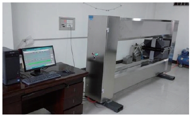
The whole experiment process includes on-line measurement and engineering operations. The experimental process of data monitoring and calculation is carried out in an on-line detection and control laboratory of paper quality. It equipped with intelligent scanner, infrared quantitative sensor, microwave moisture sensor, PC workstation and Siemens S7-300 PLC (Programmable Logic Controller) control cabinet. The experimental of CD basis weight online detection and space-time alignment algorithmic can be completed. The detection experimental platform is shown in Fig. 1.
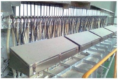
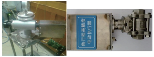
Engineering operation is based on actual paper mill equipment. For CD control system, the CD basis weight profile are adjusted by dilution valves, which are installed on the hydraulic headbox. The operation of the hydraulic headbox is shown in Fig. 2. The dilution water regulating device is shown in Fig. 3, which includes a dilution water cone pipe and multiple dilution water valves with automatic control units. One interface of the dilution water valve is connected with the dilution water cone pipe, and the other interface is provided with a water conveying hose that is connected to the pulping branch pipe. The amount of white water injected into the pulp is controlled by adjusting the opening of the dilution valve, thus realizing the local fine-tuning of the cross-directional basis weight of the paper. For dilution valves, the typical width of each valve is approximately between 30 mm to 60 mm.11) When a dilution valve is adjusted, its impact on weight profile could spread to multiple adjacent zones. The high-precision valve positioner is shown in Fig. 4.

2.2 Control method for the experimental device
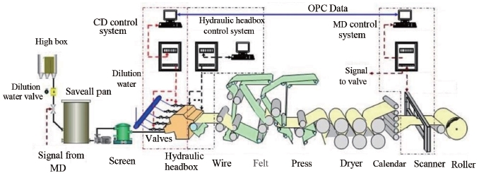
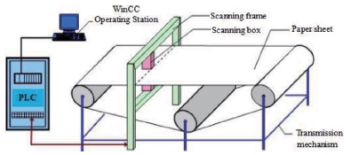
The process of CD control for a Fourdrinier machine equipped with a hydraulic headbox is shown in Fig. 5. The scanning frame as a basis weight on-line detecting device is installed between the calender and the winder of the paper machine, and the basis weight sensors are installed in the frame probe box and scan paper sheet that moves through the opening of the frame. This system continuously obtains the instantaneous sample value of the basis weight along the machine direction and its CD profiles.
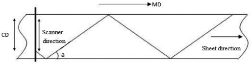
The dilution actuator setpoints are determined by the weight profile obtained from the scanning weight sensor. The sheet typically moves at a velocity on the order of 10 m/s, and the sensors typically move approximately 10-1 m/s.13) As a result, the actual measurement is taken from a zig-zag path as shown in Fig. 6, where the angle ‘a’ may be only approximately 1°.14) Moreover, the gauge stops at one side of the sheet (for some time intervals at unpredictable time instants) for recalibrating itself. From these sparse data, the whole profile can be reconstructed.
In a paper mill, the data of paper basis weight is obtained by QCS (Quality Control System) through scanning sensors. The schematic diagram of the on-line detection device for QCS data is shown in Fig. 7. The data exchange between OPC (OLE for Process Control) toolbox and configuration software of WinCC (Windows Control Center) is carried out by MATLAB (Matrix Laboratory). Then the control algorithm is realized based on the data obtained by MATLAB. The calculation results are fed back to WinCC. S7-300 PLC is adopted for the controller implementation.
3. Results and Discussion
3.1 Results
For a project of 140 g/m2 of corrugated paper produced in a factory of Northeast China, the technological indexes for the CD control system as follow:
The slice outlet width is 3,900 mm, the design speed is 650 m/min, the number of dilution valves is 64, and the installation distance of dilution valve is 60 mm.
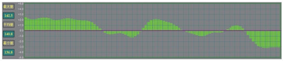
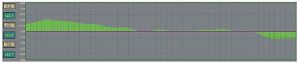
The control algorithm was integrated into the paper making process. As shown in Figs. 8 and 9, the basis weight fluctuations after the decoupling control were compared. The maximum and minimum basis weight were 142.1 g/m2 and 138.7 g/m2 in a measurement cycle. The average value of basis weight was 140.5 g/m2 and fluctuation deviation was 3.4 g/m2, the mean square deviation 2σ=1.721. It can be seen that the basis weight fluctuation range was significantly reduced, the product quality was improved based on the control system.
Based on implementation of the multivariable dimension-reduction and synergic control system for cross-directional basis weight of the papermaking process, a decoupled CD system was realized in this project. In the decoupled CD system, each single loop controlled by 64 actuators has similar physical characteristics. It is first-order with a dead-time dynamic response of the process. Each loop controller design is relatively simple. Take a two-loop adjustment for example. For each single-loop design controller, the response curve under the action of the controller is shown in Figs. 10 and 11.
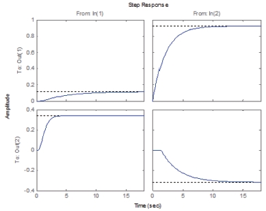
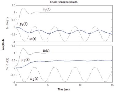
u1(t) and u2(t) represent the input signals of any two control valves, the corresponding control outputs are y1(t) and y2(t). A good output of y1(t) can be seen when the first step input of u1(t) applied to the system, and y2(t) is almost 0. The effect was found to be similar when the second input is used alone. The loops do not affect each other. It was proven that the coupling relationship has been eliminated very well.
3.2 Discussion
In a CD profile control system, the number of sheet profile measuring points may range from 200 to 2,000, and the number of actuators could be up to 300. A large number of profile points and actuator zones will inevitably show coupling problems between adjacent dilution valves. In addition, because of the spread of the flow, each actuator zone affects several adjacent zones on both sides. The final result is that when a dilution valve is moved, it affects the CD profile value of the adjacent measurement points. This leads to the control system becoming a high-dimensional, multivariable and strongly coupled system. It is difficult to control. To address actuator coupling issues, the mathematical model, coupling matrix and multiprocessor decomposition design techniques should be discussed.
3.2.1 Mathematical model of CD process
The mathematical model of a CD process consists of two parts: one part is the sparse interaction matrix across the entire width of the sheet, and the other part is the MD dynamics from the dilution water valve actuator to the measured profile.
The standard paper machine CD process model is given by
where Y(s)∈Cm and U(s)∈Cn are the measurement profile and the actuator set-point array, respectively, and G0∈Rm×n is the spatial interaction coupling matrix that describes the response of the process. It also describes the mapping from the actuators to measurements. m and n are the numbers of actuator arrays and controlled sheet properties, respectively. G0 is a block-diagonal matrix with its number of columns equal to the number of actuators and its number of rows equal to the number of profile points, where gij refers to the influence coefficient of the j-th actuator on the i-th measurement point. For a typical paper machine, there could be as many as 600 individual actuators and 6,000 profile points if all CD actuator arrays and all controlled properties are included in one control system.15) In other words, the dimensions for the multiple-array process model G(s) in Eq. 1 could be 6,000×600. g(s) is the first-order-plus-time-delay dynamic response of the process. The expressions of Y(s), U(s), G0∈Rm×n, and are g(s) as follows.
The profile of the CD is similar to an inverted ‘S’ shape,16) The stationary CD profile shape of the sheet is a two-dimensional wave, as shown in Fig. 12.
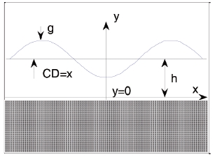
As the CD basis weight does not vary with time, then, g(x,t) can be simplified to g(x). For a continuous sheet-forming process, the relationship between the two-dimensional sheet variations g(x) and CD control action to the j-th CD actuator can be formulated as Eq. 3.17)
It is shown that the spatial response of a single controller can be represented by the extension of a set of orthogonal functions, where the spatial coordinate χ is a scalar real number, γ is a gain parameter, and ξ is a width parameter. The parameters γ and ξ define the linear transformation of the response by stretching it vertically and horizontally, respectively. The attenuation parameter α changes the size of the negative lobes of the response. The divergence parameter β defines the presence of two maxima in the response and the distance between these two maxima.
3.2.2 Coupling matrix analysis and identification
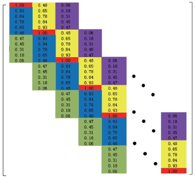
In the experimental simulation, taking a dilution water hydraulic headbox with 64 dilution water valves as an example, the measurements and the actuator form a large-scale interaction coupling matrix with dimensions of 320×64. Based on such an example, a large-scale interaction coupling matrix G0 can be described as Eq. 4. The parameters g1, …, g26 describe the spatial response of the process, where 26 is the half-width of the response of one actuator and m represents the scanning space between adjacent actuators.
The coupling matrix G0 can be calculated. G0 is a sparse band-diagonal matrix with a large number of zero elements. As shown in Fig. 13, where the non-zero data reflect the coupling coefficient of each CD position and the strip width reflects the strength of the coupling.
3.2.3 Dimension-reduction and decomposition
For non-square high-dimensional coupling systems, it is necessary to adopt a suitable method to reduce the system dimension and convert it into a square system for decoupling. According to the strip coupling width of the above interaction matrix, G0 is standardized as shown in Fig. 14, where p is the coupling width, which indicates the number of affected actuators on the adjacent side when adjusting an actuator (p=2 in this paper), and 2p+1 is the strip width.
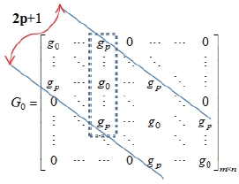
For simplifying the analysis, a blocking-based triangulation strategy is adopted for the coupling matrix G0. Along the diagonal, the coupling matrix can be divided into q×q block matrices. Thus, G0 can be partitioned as
where ([ ] is the rounding up function, for example, [h] represents the smallest integer that is no less than h). G1 is an upper triangular (2p+1)×(2p+1) matrix, and G2 is a symmetric (2p+1)×(2p+1) matrix. The structures of G1 and G2 are given by Eq. 6.
Based on such a division, an m×n-dimensional CD control system is divided into q groups, and each group contains 2p+1 subsystems, where the model of the subsystem can be expressed as Eq. 7.
For subsystem Yj(t), the symmetric parts of 2 and 3 in expression Eq. 7 correspond to the paper CD basis weight boundaries. The block matrix G1,G1T is located at the boundary of the interaction matrix, and G2 is located on the main diagonal of the interaction matrix. When the effect controlled by G2 is non-zero and the other parts of the control effect are zero, G0 can be converted to a main diagonal matrix. Then, the system can be simplified as a main diagonal system, and the coupling can be reduced. Based on the input variable adjustment, the decomposition algorithm is adopted to eliminate the control effect of sub-blocks 2 and 3 in this paper.
At one moment, each actuator rotates in a sequence of Eq. 8,
Cyclically input the control variables in chronological order. Actuators belonging to different groups can act simultaneously.
During the period from t to t+2p+1, efficient control inputs [u1,u2,…,uq] (q=64) (such as Eq. 9) are applied to the 320×64 CD system.
Based on these control inputs, the original high-dimensional non-square CD control system (320×64) can be converted to a new low-dimensional CD system (64×64), which can be described as Eq. 10.
For the new low-dimensional square system, the interaction matrix with a number of dimensions equal to the number of actuators and a one-to-one correspondence between the CD measuring point and the actuator is solved. The new interaction matrix can be given as Eq. 11.
Moreover, the new interaction matrix is a Toeplitz symmetric matrix. = Toeplitz(f), where f = [1,0.7,0.3,0,…0].
In the case of ignoring the edge effect, the entire paper web and the mechanical structure are symmetrical.18,19) Based on the control input, the new diagonal interaction matrix represents the new structure of the system. is given by Fig. 15.
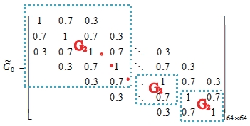
Where the details of G2 in the matrix of can be described as Eq. 12.
Next, the coupling characteristics of the new system were studied by the relative gain, and for the new CD system, the relative gain matrix of the system was calculated. The interception part of the calculation results was shown in Fig. 16.
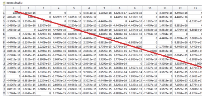
According to Fig. 16, the main diagonal element of the relative gain matrix is 1 (marked with a red line), the other elements are approximated to 0 after taking the truncation error, and the matrix can be approximated as a 64×64 unit matrix,20,21) as shown in Eq. 13.
where Λ is the relative gain matrix. According to the relative gain characteristics, the relative gain matrix of the decoupled system must be a unit matrix.22,23) This conclusion also applies to multivariable systems.
This result indicates that the original large CD system was converted to a new CD square system based on the steps of system dimension reduction and block alignment calculation. For the new system with 64 dimensions, there were 64 actuators mapping 64 regions, which means that the coupling between each region was eliminated.
4. Conclusions
This paper presents a novel control strategy that efficiently addresses the issue of the strong coupling in the large number of cross-direction actuators with which sheet-forming processes are equipped. The method employs a new block decoupling algorithm for the MIMO (multi-input multi-output) process, the matrix block method and model reduction were applied in the interaction coupling matrix of dimensions of 320×64, and the original 320×64 non-square CD control system can be converted to a new low-dimensional CD system with dimensions of only 64×64. The algorithm decouples a high-dimension multivariable system into several low-dimension subsystems. In this algorithm, a new constraint on the control input was constructed to satisfy the triangular decomposition of the subsystem, and a parallel control structure was designed to implement the algorithm. Based on the multi-actuator parallel control strategy, a decoupled multivariable system was achieved. The mathematical values for the real CD actuators were computed and implemented in the plant. The solution from the decoupled system was then projected back to the original space for implementation in a real paper mill. Simulation examples were included to illustrate the method, and it was shown that the coupling effect can be significantly eliminated and the system real-time performance can be improved.
