

1. Introduction
The basis weight indicator includes the machine direction (MD) and cross-direction (CD).1,2) It is an important technical indicator of paper. The technological process for basis weight control is shown in Fig. 1.3)
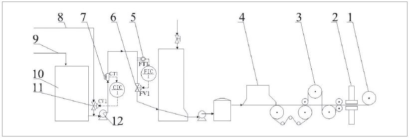
Fig. 1.
Technological process for basis weight control in the paper machine. 1. Reeling machine, 2. Scanner, 3. Dryer, 4. Headbox, 5. Flow transmitter, 6. High-precision basis weight control valve, 7. Consistency transmitter, 8. White water, 9. Pulp, 10. Pulp storage, 11. Consistency control valve, 12. Pulp pump.
After pulping process, the pulp slurry is sent to a pulp storage tank, and then it is diluted with white water through a consistency control loop (CIC1) to make the consistency steady. A valve (CV1) is used to adjust the flow of white water, and the pulp consistency transmitter (CT1) is used to detect the real-time consistency of the pulp. Through this method, the consistency of the pulp slurry was controlled at a stable value. Because of the basis weight of paper equals to the product of consistency and the flow rate of pulp slurry. So, the basis weight was controlled by flow of pulp slurry as the consistency was a constant value. The pulp slurry flow rate is controlled by the flow control loop (FIC1) to cause a steady flow, the flow control valve (FV1) is used to adjust the flow rate of pulp, and the flow transmitter (FT1) is used to detect the real- time flow rate of pulp slurry to form a control loop. The pulp was diluted to a much lower value by flow past a white water tank. And then, the pulp slurry was sent to the head-box to form wet web. The wet web was dried in a dryer section where the dryers are filled with steam. To achieve automatic basis weight measurement and control, quality control systems (QCS) are installed in the paper machine.4) The real-time basis weight of MD and CD are measured by a scanner installed in front of the reeling machine. The basis weight of MD is controlled by the flow control valve. The basis weight of CD is controlled by the dilution profile actuators, which was installed at high density in the cross-direction of the dilution hydraulic headbox. This paper primarily discusses the flow control valve (FV1).
As the basis weight of the paper is fully controlled by the flow control valve, the valve must have high precision. The typical accuracy of a valve was 5,000 steps to 20,000 steps. The accuracy of the valve is represented by the number of steps. The travel range of the valve stem is 0°-90°. It is divided into many same-size angles. Each unit is called one step. For example, the nominal accuracy value of a valve is 10,000 steps. This means that 10,000 control pulse signals could make the valve rotate from 0° to 90°. The minimum rotation angle of the valve stem is 0.009°. The error value should be lower than the rotation angle of each step. The rotation angle of the valve stem should have a strictly direct proportion to the number of control pulse signals. Even the valve runs at reverse direction. It needs a high accuracy of the valve. The error rate of a common electric control valve or pneumatic control valve is too large to meet the precision requirements of the process technology. A type of special product was developed to meet the requirement of high precision. It was called the basis weight control valve.5-7)
The main differences between the basis weight control valve and a common electric control valve are the drive system and the transmission system. The basis weight control valve is commonly driven by a stepper motor to achieve precise positioning of the drive system. A high-precision reducer is used to transmit the angular displacement of the stepper motor to the valve stem. To reach the high accuracy of the application, a high precision transmission element was recommended. A harmonic reducer was installed in the valve; the typical value of backlash was lower than ±15 arcsec.8) Because the backlash value is too small to be expressed by the unit of degree, a unit “arcsec” is used to express the backlash value. One degree equals 3,600 arcsec. Because the rotation angle during the full travel range of the valve is 0°-90°, it equals 324,000 arcsec. Each control pulse signal makes the valve stem rotate for 32.4 arcsec, when the number of operating steps is set at 10,000 steps. The error range of the backlash value is less than each single step. Therefore, the error can satisfy the accuracy of the valve. However, the cost of the harmonic reducer is very high. It has restricted its promoted application because of the high price of the basis weight control valve.
Many research works were conducted to reduce cost and improve the precision of the valve. A type of valve with lower cost has been developed. It was comprised of an actuator, a V-type ball valve and a controller.9,10)Fig. 2 illustrates the mechanical structure and control principle. The stepper motor fits on a planetary reducer, and the reducer is fixed to a support plate. The ball valve and actuator are bound together with screw bolts. The torque is transmitted by a high-rigidity coupling, which connects the valve stem and the output shaft of the reducer. A valve position indicator was installed on top of the actuator shell.
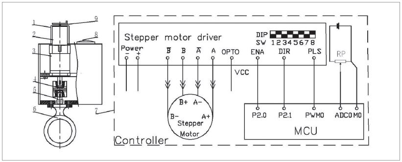
Fig. 2.
Typical mechanical structure and controller for the basis weight control valve (Take an example of the valve developed by the authors’ research group). 1. Motor cover, 2. Stepper motor, 3. Planetary reducer, 4. Coupling, 5. Valve shaft, 6. V type ball valve, 7. Controller, 8. Valve position indicator, 9. Hand wheel.
As the valve was drive by a stepper motor. The phenomenon of “pulse losing” will happened if the acceleration rate of the stepper motor was too high when the control pulse was generated as constant frequency. In order to improve the positioning precision of the stepper motor itself, research works has been carried out by author’s research group. The method of the trapezoidal velocity curve was adopted to make the stepper motor running more smoothly. So the precision of the stepper motor has been improved.11) As a stepper motor driver was adopted to transmit the control signals into greater drive current. Then the stepper motor could be controlled by the valve controller. It’s difficult to determine the drive current value of the stepper motor driver. The drive current value of the driver was set at the rated current value of the stepper motor in most case. The drive current value could hardly match with the rated design torque of the valve. In order to find the reasonable drive current value of the stepper motor driver, the experimental research work also was carried out by author’s research group. The drive parameters such as reasonable drive current value, state holding current value and the acceleration time of the trapezoidal velocity curve were obtained.12)
The planetary reducer was thought to have enough accuracy and its cost was reasonable. It has a much lower price than the harmonic reducer. However, the backlash was not measured, and the exact value was not known, as the value was thought to be very small. Even it was thought has less influence on the accuracy of valve. The backlash was neglected in most case. However, the accuracy of the valve could not meet the requirement of field applications. The cause of this problem was found through analysis of the differences between the new type valve and the former one. Both of the valves were driven by stepper motors. The main distinction was the transmission mechanical system. One is planetary reducer, another is harmonic reducer. The precision of the two was different. The backlash error of the harmonic reducer was much lower than the planetary reducer. The rotation angle of the valve stem could maintain a strictly direct proportion to the number of control pulse signals. The rotating direction of the motor changes from forward to reverse continuously when the valve works. The phenomenon of accuracy loss was caused by the backlash when the valve moves at reverse direction. The valve stem will not move if the displacement increment of the control pulse signal is less than the backlash value. So the flow rate was not changed as the valve opening was stayed at the former position. Another situation is that, the opening value of the valve stem will be less than the theoretical value of the control pulse signal. It will cause the nonlinear problem in the control process.
The average backlash range of the planetary reducer is ±11 arcmin, according to the manual.13) (Because the backlash value is too small to be expressed by the unit of degree, a unit “arcmin” is used to express the backlash value. One degree equals 60 arcmin.). Use an ordinary planetary reducer as an example. Because the rotation angle during the full travel range of the valve is 0°-90°, it equals 5,400 arcmin. The backlash error range accounts for 0.204% during the full travel range of the valve. The error range should not exceed the minimum operating step. The precision of the valve should not be lower than the reciprocal of error rate. The accuracy is lower than 490 steps if the error of backlash is neglected.
As seen, the backlash has a significant influence on the precision of the valve. If the backlash could be compensated, the precision of the valve which equipped with the planetary reducer will be greatly improved. The low-cost basis weight control valve could be used in high precision conditions. So the backlash in basis weight control was conducted in this study.
2. Materials and Methods
The actual backlash value of the transmission mechanical structure should be tested. Because only the average backlash range was given by the planetary reducer manufacturer, an accurate value was not mentioned. The actual backlash value should be measured first.
2.1 Development of a testing device for the backlash value and pulse signal
An experimental device was developed to measure the backlash value. As shown in Fig. 3, an optical rotary encoder was installed on the back shaft of the stepper motor, which was used to measure the rotation angle of the stepper motor. Similarly, another optical rotary encoder was installed on the output shaft of the valve actuator, which was used to measure the output rotation angle of the actuator. The output shaft of the actuator and the output shaft of the planetary reducer were connected by a coupling because the rotation of the valve stem was prevented by the seals. However, the experimental device was not connected with the real valve. A pair of friction plates was fixed on the baseplate and used to prevent the movement of the output shaft, which was used to make sure the movement of the output shaft of the actuator coincided with the actual valve. In this way, the backlash of the transmission mechanical system could appear. If there was no load torque applied to the output shaft, the backlash would not appear as the reason for the free movement of the output shaft.
2.2 Design of the control system for the experimental device
The capabilities of the control system include controlling the movements of the stepper motor, measuring the rotation angle of the stepper motor and the output shaft. The electrical control system schematic of the experimental device is shown in Fig. 4. The PLC (programmable logic controller) was the key part of the control system. A highspeed pulse signal was generated by the output terminal (Q0.0); it was connected with the pulse signal input terminal (PLS) of the stepper motor driver. The directional signal was controlled by terminal (Q0.1) of the PLC, and it was connected with the direction signal input terminal (DIR). The torque of the stepper motor was controlled by the enable control terminal (ENA) of the motor drive, and it was connected with the terminal (Q0.2) of the PLC.
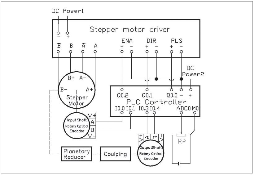
Two optical rotary encoders were used to measure the accurate rotation angle of the input shaft and output shaft of the transmission mechanical system. The resolution of the input shaft optical rotary encoder was 1,000 pulses per revolution. The resolution of the output shaft optical rotary encoder was 5,000 pulses per revolution. The A and B twophase pulse signal of the two optical rotary encoders was sent to the high-speed input signal channels of the I0.0 and I0.1; I0.3 and I0.4 terminals. Thus, the rotation angles can be measured by the controller. The mode of the A/B-phase quadrature counter is configured in the controller.14) Therefore, the count value of the input shaft encoder reaches 4,000 pulses per revolution, and the count value of the output shaft encoder reaches 20,000 pulses per revolution. A variable resistor potentiometer is connected to the analog input channel of ADC0 and M for detection of the valve opening position.
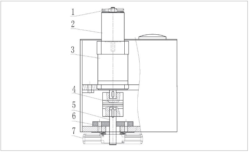
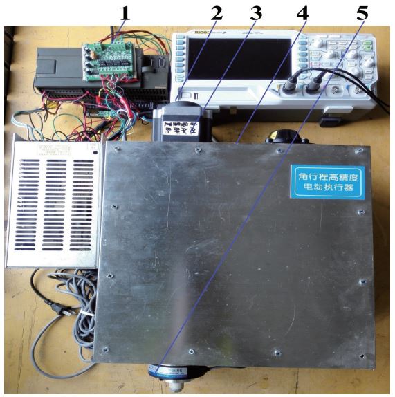
The total experimental device is shown in Fig. 5. The rotation angle of the input shaft and output shaft could be measured by the two optical rotary encoders. The backlash value of the transmission mechanical structure could be measured.
2.3 Test of the backlash value of the transmission mechanical structure
The backlash appears at the reserve moment. First, the valve was rotated forward direction to a certain position (valve opening position is shown in letters θv). Then, the two registers which stores the value of the input shaft encoder and the output shaft encoder were cleared. Second, the stepper motor was rotated forward direction as a precise full revolution. The input shaft encoder which installed on the back tail shaft of the stepper motor was used to make sure of the precise positioning of the stepper motor by closed-loop position control. Third, the stepper motor was rotated backward direction as a precise full revolution. The count value of the output shaft encoder was represented as ns. Then, the rotation angle of the output shaft (θs) was measured by the controller.
The backlash value (θb) of the transmission mechanical structure is shown as Eq. 1.
where θb is the backlash value backlash value (its unit is arcmin), ns is the count value of the output shaft encoder, and θv is the current valve opening value. The units of the θv and θs are degree.
The backlash value during the full travel range of the basis weight valve could be measured in this way. To represent the average backlash value, the average backlash value (θbe) of the transmission mechanical structure during the full travel range is calculated. To judge the error distribution, the mean square error (MSE) is resolved.15) The average value is considered to be reasonable to represent the backlash value during the full travel range if the MSE value is lower.
2.4 Methods of the software compensation for the backlash
The backlash should be compensated when the current rotation direction was reversed from the last positioning process.16-18) It does not need to be compensated when the current rotation direction was the same as the last positioning process. Therefore, whether the backlash must be compensated should be judged first. The method is shown as follows.
The rotation direction of the current positioning process was symbolized by letters “M01”. The rotation direction of the last positioning process was symbolized by letters “M00”. Because the binary code was more suitable for programs and calculation, the numerals “0” and “1” express the forward direction and the backward direction of the stepper motor. The subtraction value of “M01” and “M00” (M02) was calculated. If the current rotation direction was the same as the last one when the subtraction value was 0, there was no need to compensate the backlash. Conversely, the backlash should to be compensated when the subtraction value was not equal to the value 0.
Because the valve was driven by a stepper motor, the number of control pulse signals (nb) equal to the backlash value should be added to compensate for the backlash, as shown in Eq. 2.
where nb is the number of control pulse signals that equals the backlash value, θbe is the average backlash value (its unit is arcmin), n is the reduction ratio of the planetary reducer, and s is the subdivision rate of the stepper motor driver.
The total number of pulses (nt) that drives the stepper motor of the valve should add the number of pulses that equals the average backlash value when the positioning direction was reversed from the last positioning process, as shown in Eq. 3.
where nt is the total number of control pulse signals generated to the stepper motor driver, np is the number of control pulse signals that equals the target rotation angle of the stepper motor, nb was shown in Eq. 2, and M02 is the subtraction value between “M01” and “M00”. In this way, the backlash of the valve’s transmission mechanical system can be compensated. The compensation method could be translated into the control program running in the valve controller. So the backlash could be compensated by software.
3. Results and Discussion
3.1 Test result of the backlash value of the basis weight control valve
Because the travel range of the ball valve is 0°- 90°, it rotates a quarter revolutions. The reduction of the planetary reducer is 200:1. The stepper motor will rotates 50 revolutions during the full travel range of the valve. Each control pulse signal could make the stepper motor rotate 1.8°, if the stepper motor driver was set at “full step” mode.19) A 200 control pulse signal could make the stepper motor rotate a precise full revolution. The operating number of the control pulse signal is 10,000. This means that the number of the operation step of the valve is 10,000 steps during the full travel range of the valve.
The backlash appears at the reverse moment. The backlash value of the transmission mechanical structure was tested as follows.
(1) The valve was moved to a certain valve position (θv) forward direction.
(2) Both of the two registers which stored the value of the input shaft encoder and the output shaft encoder were cleared.
(3) A 200 steps control pulse signal was generated to make the stepper motor rotates forward direction as a precise full revolution.
(4) After the motor was stopped, another 200 steps control pulse signal was generated to make the stepper motor rotates backward direction as a precise full revolution.
(5) The count value (ns) of the register which stored the rotation angle of the output shaft was recorded. And then, the backlash value could be calculated according to Eq. 1.
The backlash value of the valve is shown in Table 1. This table indicates that most count values of the output shaft encoder were distributed from 12 to 14. As shown in Eq. 1, the average backlash value (θbe) was 13.32 arcmin. Positive values are used for the count value of the output shaft since the backlash always appeared at the reverse movement. The absolute error is equal to the relative error. The mean square error (MSE) was 0.711, the percentage of MSE is 5.79%, which was almost equals to 5.0%. This illustrates that the distribution of the backlash was uniformly distributed on the typical travel range of the valve. The average backlash value was suitable to represent the full travel range.
Table 1.
Backlash value of the output shaft
The backlash error range accounts for 0.247% during the full travel range of the valve. The accuracy is lower than 405 steps if the error of backlash was neglected. It confirms that the backlash has a significant influence on the precision of the valve.
As shown in Eq. 2, the number of control pulse signals (nb) equal to the backlash value could be calculated. The pulse equivalent value was 24.69. It should be only integers. Considering that there was a large error if the value was rounded to 24 or 25, the subdivision control method was adopted to make the stepper motor move with smaller step angles.20,21)
The subdivision rate of the stepper motor driver has levels: 2, 4, 8, 16, 32, 64, and 128. The result was 395.04 if the value of 24.69 is multiplied by the number 16. The decimal part 0.04 has little influence on the total value of 395.04. The pulse equivalent value was 395, and the subdivision rate of the stepper motor driver was set at 16. The stepper motor will rotate 0.1125° when each pulse signal was generated to the driver.
3.2 Test result of the positioning precision by soft compensation
The pulse equivalent of the backlash value was added to the reverse direction positioning process, as shown in Eq. 3. The test processes were as follows.
(1) The valve was moved to a certain valve position (θv) forward direction.
(2) Both of the two registers which stored the value of the input shaft encoder and the output shaft encoder were cleared.
(3) A 3,200 steps control pulse signal was generated to make the stepper motor rotates forward direction as a precise full revolution.
(4) After the motor was stopped, another 3,595 steps control pulse signal was generated to make the stepper motor rotates backward direction as a precise full revolution.
(5) The count value (ns) of the register which stored the rotation angle of the output shaft was recorded. And then, the positioning error could be calculated according to Eq. 1.
The position error of the output shaft is shown in Table 2. This table indicates that most count values of the output shaft encoder were distributed between -1 and 2. As shown in Eq. 1, the average backlash value (θbe ) was -0.154 arcmin. The relative error was really very small. However, the size and the influence of the error were better represented by the absolute value. The average absolute error value of the output shaft was 0.977 arcmin. The percentage of the position error compared to the full travel range was 0.0181%. The accuracy is 5,525 steps when the error of backlash was compensated, which was more than 13.6 times the former without compensation. These results confirm that the method of software compensation has a significant benefit for the precision of the valve. And the method could be used easily realized in engineering practice and without increasing any hardware cost.
Table 2.
Position error of the output shaft by soft compensation
3.3 Discussion
The accuracy of the software compensation has significant relationship with the precision of the measuring component. The resolution of the optical rotary encoder used in this paper was 5,000 pulses per revolution. To achieve higher measuring accuracy, an optical rotary encoder or circular grating with much higher resolution such as 10,000 pulses/revolution or 65,536 pulses/revolution would be much better.22)
The transmission mechanical system of the valve actuator includes the reducer and the coupling. The coupling is installed on the output shaft of the reducer. It is the last transmission part. The last part has much more influence on the total precision of the actuator; therefore, the coupling is an important part of the actuator. To reduce the impact of the error, a solid coupling was recommended. The feature of this solid coupling is rigid transmission, without any backlash. It is not recommended to install an elastic coupling or flexible coupling in the actuator.
The precision of the valve was expressed as steps. Sometimes, the precision value was confused with the operating steps of the valve. The methods of stepper motor subdivision control could improve the number of operating steps. However, if the minimum operating steps was lower than the error of backlash, the backlash will have a significant influence on the precision of the valve. Although the number of operating steps was large, the error will appear at the reverse movement. However, the accuracy of the valve was not improved significantly only through increase of the subdivision rate of the stepper motor driver.
4. Conclusions
The flow rate is proportional to the opening value of the valve. The method of backlash software compensation was helpful to improve the precision of valve opening value. So the flow rate of the pulp slurry can be precisely controlled. The precision of the valve was higher than 5,000 steps. Although it was lower than a valve equipped with a harmonic reducer, it is quite satisfactory for practical application. The lower-cost basis weight control valve which equipped with planetary reducer could be widely used in not only in pulp and papermaking industry but also in other process industry.
