

1. Introduction
2. Physical Model, Mesh Division and Calculation Method of Distributor
2.1 Physical Model and Mesh Division
2.2 System Dynamics Model
2.3 Boundary Condition Setting and Calculation Method
3. Numerical Simulation Results
3.1 Velocity Distribution
3.2 Pressure Distribution
3.3 Mass Flow Distribution of Branch
3.4 Influence Law of Parameters
4. Structural Optimization
5. Conclusions
1. Introduction
In modern high-speed paper machine pulping, the headbox mostly adopts the rectangule-tapered distributor with Baines-type total tube and branch pipe,1) whose function was to spread the pulp suspension evenly and stably along the paper machine banner. Its efficiency directly determines the performance of the whole headbox. Therefore, it was of great significance for the paper industry to study the flow law in the distributor. At present, scholars at home and abroad have done some work on the design theory, optimization and experiment of the distributor. Youn2) tested the flow performance for three kinds of turbulence generator (step diffusor) by pulp injection method; HümüLüinen3,4) carried out the flow simulation and shape optimization of a rectangule-tapered distributor with self-made calculation program; Sumida 5) carried out the flow experimental research on a hydraulic headbox model of paper machine; Liu6) made a comparative study of Baines simplified type distributor, segmented approximate type distributor and improved type distributor; Hou7,8) used Proe and ANSYS CFX softwweres to simulate and optimize the structure of a multi seam type distributor; Kang9) used UG and Fluent softwweres for numerical simulation and parameter analyswas ofa distributor flow field; Zhou10) carried out the pulp flow mechanwasm and channel structure design of a dilution water hydraulic headbox. However, the above studies have all ignored the unsteady secondary flow (vortex) or the separation of fluid from pipe11) wall when the fluid passes through sharp elbows or gates, which will lead to the flow unevenness in many fluid machines.
The design of the feed manifold for pulp distributors had always been a key issue in modern high-speed paper machines. In order to solve the problem of uniform lateral pulp distribution, modern large-scale paper machines often used a single side feed conical manifold for pulp distribution in their headboxes. Currently, there were three main types of branch pipes, namely bow shaped conical tubes, circular conical tubes, and rectangle-tapered. The branch pipe for pulp distribution was usually composed of transition tubes, conical tubes, and pulp distribution components.12) Currently, the vast majority of pulp distributors in headboxes used rectangle-tapered. To ensure the uniformity of the quantitative distribution of paper sheets, it was necessary to make the flow velocity and pressure of the pulp entering each bundle equal. In the design of equal pressure rectangle-tapered. The Baines equation is usually used to calculate the cross-sectional dimensions of a conical tube.13)
The flow unevenness of pulp in rectangle-tapered distributor will have a negative impact on the paper properties, so it was necessary to study the flow law and the measures to eliminate the uneven effect for the distributor. Referring to the computational fluid dynamics (CFD) method for heat exchanger14) and stripper,15) in this paper, the CAD and CAE softwweres were combined to simulate the flow field of pulp in rectangule-tapered distributor with Baines-type total tube (the cross-sectional shape and taper of total tube were designed using the Baines equation, which only considers the frictional head loss of the pulp flow inside the total tube and does not take into account the bifurcation head loss and contraction head loss) and branch pipe. The influence of backflow and branch length on the flow distribution of distributor was dwascussed, and the structure of distributor was designed innovatively, so as to improve the uniformity of overall pulp. These provide a theoretical baswas for practical application.
2. Physical Model, Mesh Division and Calculation Method of Distributor
2.1 Physical Model and Mesh Division
The basic data of the paper machine was: the quantitative measurement of fiber raw materials was 11–15 g/m2, a net paper width of 3600 mm, a design speed of 1200 m/min, and a production capacity of approximately 60 t/d. The specific design parameters of a distributor were as follows: the total length L of total tube was 1800 mm, the total width B of inlet section was 300 mm; the working speed of headbox was 1200 m·min-1; the total flow was 240 kg·s-1, and the backflow flow was 10% ; the velocity of pulp flow at the inlet end was 4 m·s-1, so the height H0 at the entrance of total tube was 200 mm; the ratio of the pulp flow velocity in branch pipe to in total tube was 3, so the diameter of branch pipe was 19.6 mm; there were 60 branch pipes, which were evenly divided into two rows, and there was a row of branch pipes on the center line of total tube; the spacing of each branch was 60 mm, and the branch length was 100 mm. Due to the concentration of the pulp entering the cone tube is generally less than 1%. Its density and viscosity are close to water. Therefore, in the calculation, water was used to approximate the pulp.
The total tube was divided into 10 sections. According to the calculation formula of Baines,16) the sectional area value of rectangle-tapered total tube was shown in Table 1.
Table 1.
Design value of tapered section
The specific meanings of the parameters in the Table 1 can be found in the literature.17)
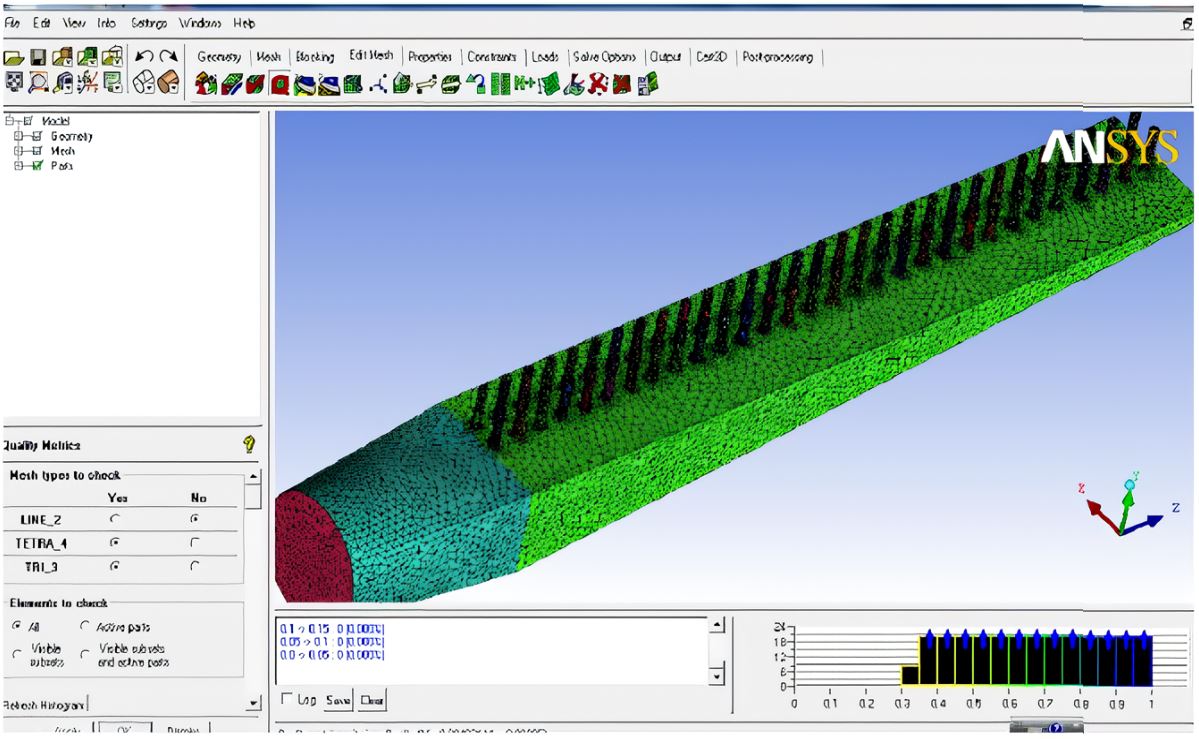
Establwashing corresponding geometric model of total tube based on the cross-sectional area along the axis of the main pipeline and the corresponding height and width values in Table 1. The size (length) of transitional part from the inlet pipe to rectangle-tapered distributor inlet was 150 mm. In the direction of elongation, the cross-section of the transition tube gradually changes from circular to square. The 3D softwwere UG was used for geometric modeling, which was exported as Parasolid type file, and then importing it into ANSYS ICEM CFD 13.0 softwwere for tetrahedral mesh generation (mesh size was 2 mm, number of mesh was 548125). Tetrahedral meshes were suitable for fast and efficient meshing of complex geometric models. When using ICEM CFD to mesh complex geometric models, tetrahedral meshes can be automatically generated. And it can generate structured and unstructured grids with multiple topological blocks. When generating grids, automatic refinement of boundary layer grids, local refinement of grids in area with severe flow field changes, and simulation of separated flows can be achieved. The physical geometry model of the rectangule-tapered distributor with Baines-type total tube and branch pipe was shown in Fig. 1.
2.2 System Dynamics Model
When the pulp flows into the rectangle-tapered total tube through the transition section of distributor, the total tube region was treated as a three-dimensional steady-state incompressible turbulent flow. Its control equations17) include:
(1) Continuity equation
Here , , were the velocity components of velocity vector on axis, and 𝜌 was fluid density.
(2) Momentum equations
Here was projection of -direction shear stress in -direction, was microelement pressure, and , , were the components of volumetric force per unit mass fluid.
(3) RNG equations
Here 𝜀 was dwassipation rate, was turbulent kinetic energy, , were the reciprocal of Prandtl number, was effective vwascosity coefficient, was velocity turbulent kinetic energy, was buoyancy turbulent kinetic energy, was pulsating expansion,, were the model constants, and , were custom source items.
2.3 Boundary Condition Setting and Calculation Method
Importing the Fig. 1 into ANSYS-CFX, the physical property of pulp was similar to the water, the inlet condition of distributor was set as velocity flow 240 kg·s-1, the outlet condition of distributor was set as velocity flow 24 kg·s-1, the outlet condition of each branch pipe was set as pressure flow one standard atmospheric pressure, and the wall condition was set as no sliding. Structured grid was used in the spatial region, the second-order upwind difference scheme was used for the dwascrete terms, and the SIMPLE algorithm was used for the pressure-velocity coupling term. When the solution error reaches 10-4 level, the calculation was over.
3. Numerical Simulation Results
3.1 Velocity Distribution
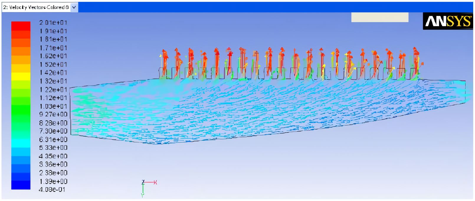
Viewing from the vertical center plane of the distributor, the Fig. 2 shows that the velocity of pulp flow was not exactly the same in the whole total tube. On the entire central plane, the velocity was not exactly the same. On the rear wall side near the pulp distributor, the velocity slightly decreases from the pulp inlet to the outlet, while at the reflux outlet, the velocity returns to a similar level as the pulp flow velocity at the inlet. this was because the design process of the pulp distributor takes into account the existence of head loss, so the cross-sectional area of the main pipe was slightly larger than that of the constant velocity pulp distributor, in order to slightly reduce the average velocity of the pulp flow on the cross-section and obtain more head recovery. At the outlet of each branch pipe, the pulp flow velocity was roughly the same.
3.2 Pressure Distribution
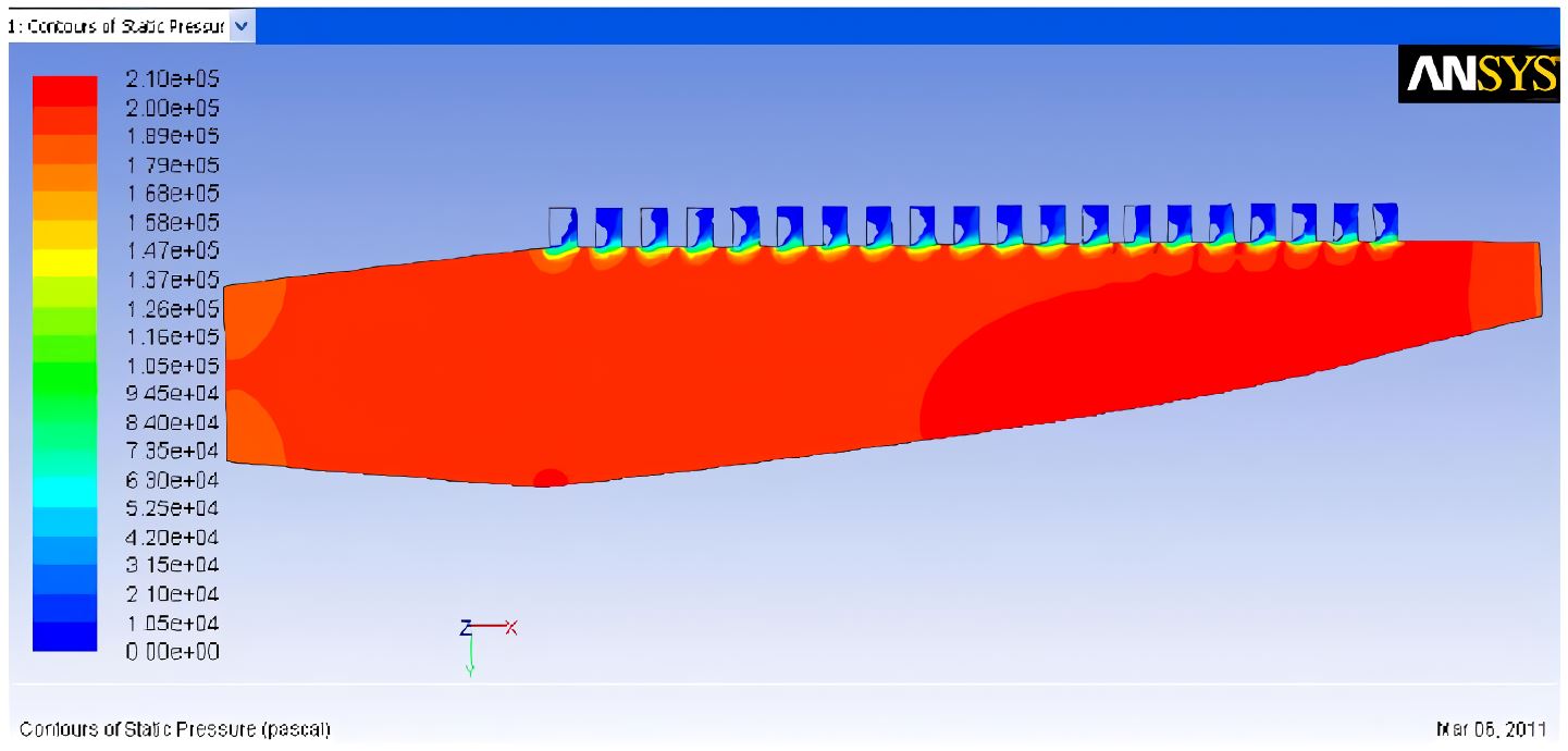
According to Bernoulli's principle, the pressure was inversely proportional to the velocity. Viewing from the vertical center plane of the distributor, the Fig. 3 shows that at the entrance of branch pipe, there was an area where the pressure was less than 0 (cavity), the cavity means no flow region by vortex, and along the branch length, the pressure was on a downward trend. There was an obvious pressure up-gradient from the inlet to the outlet of total tube, and the pressure was close to the inlet value at backflow end.
3.3 Mass Flow Distribution of Branch
Along the flow direction of total tube, each column of branch pipes was named as 1, 2, ..., 30. The Fig. 4 shows that the maximum of branch exit mass flow was the column 30 and the minimum of branch exit mass flow was the column 1. This was consistent with the pressure distribution pattern in the main pipeline, because according to Bernoulli's principle, the inlet pressure was low and the pressure gradually increases along the flow direction of the main pipe. Importantly, it is closely related to backflow rate. Meanwhile, the exit mass flow of each branch fluctuates around the expected value, but the trend undulations, so there was obvious unevenness.
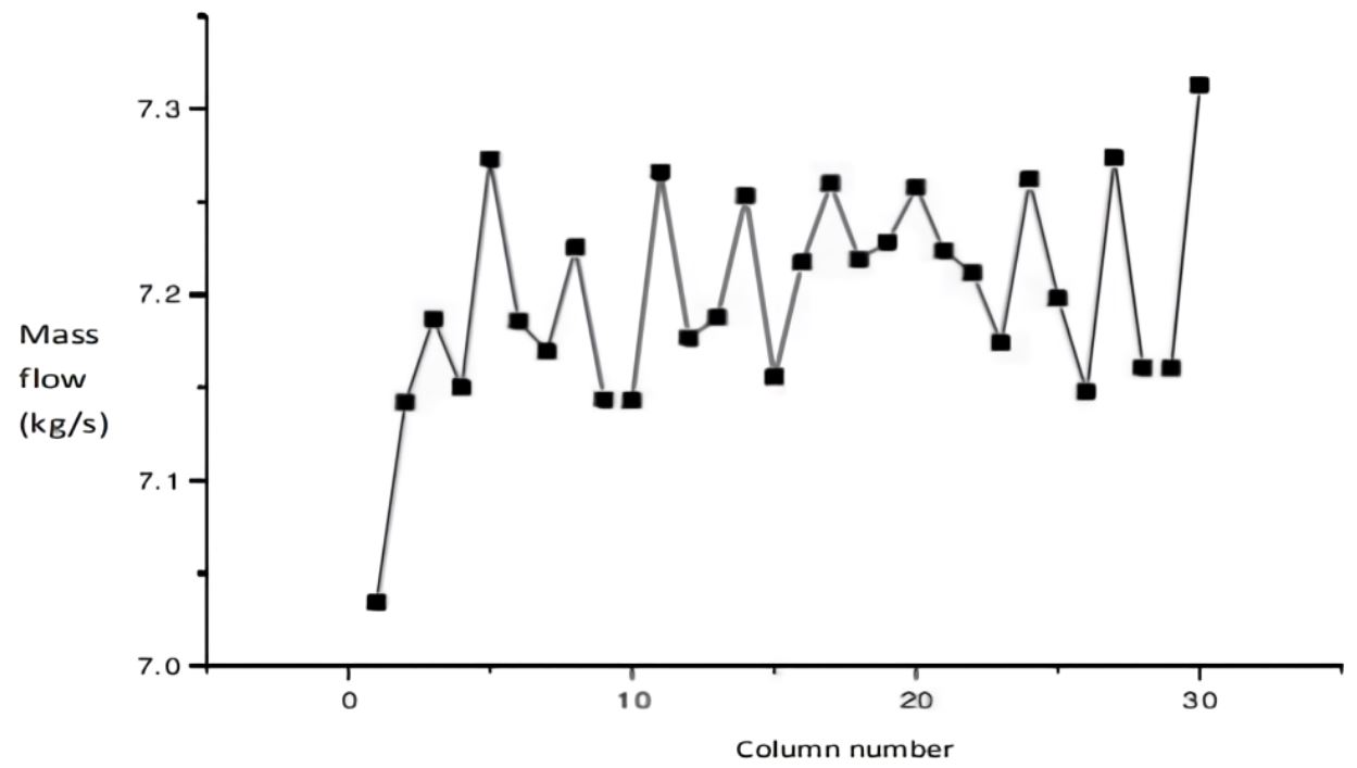
There was a change in the flow pattern at almost three branch pipe intervals. this periodicity was not due to the simulation mesh size, the flow of pulp from the main pipe to the branch pipe bundle was a 90° turning flow. this large angle turning flow not only causes significant bifurcation losses, but also creates a vortex zone at the entrance of the branch pipe bundle, causing significant pressure fluctuations downstream of the branch pipe and resulting in unstable flow.
3.4 Influence Law of Parameters
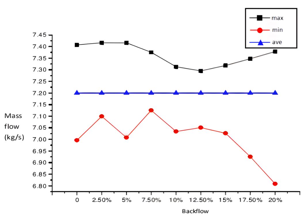
Backflow and branch length were important process parameters of headbox total tube. (1) Fixing other parameters. When the backflow was 0, 2.5%, 5%, 7.5%, 10%, 12.5%, 15%, 17.5% and 20% respectively, the maximum, average and minimum values of branch pipe mass flow were shown in Fig. 5. The Fig. 5 shows that the average value was not sensitive to the change of backflow. Within the range of this study, when the inlet flow rate was 4 m·s-1 and branch diameter was 19.6 mm, and when the backflow was 12.5%, the difference between the maximum value and the minimum value was the smallest, then the homogenization effect of distributor was the best.
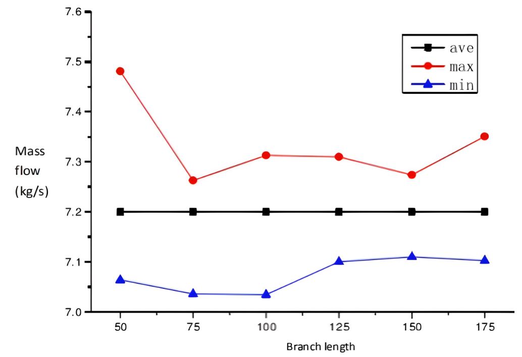
(2) Setting the backflow was 10%. When the branch length was 50 mm, 75 mm, 100 mm, 125 mm, 150 mm and 175 mm respectively, the maximum, average and minimum values of branch pipe mass flow were shown in Fig. 6. The Fig. 6 shows that the average value was not sensitive to the change of branch length. When the branch length was 150 mm, the difference between the maximum value and the minimum value was the smallest, and the pressure fluctuation in the branch pipe was smaller, then the homogenization effect of distributor was the best. Generally, the branch length was at least 6 times of diameter needs to fully develop the flow. Within the range of this study, when the inlet flow rate was 4 m·s-1 and branch diameter was 19.6 mm, the best branch length was suggested as 150 mm.
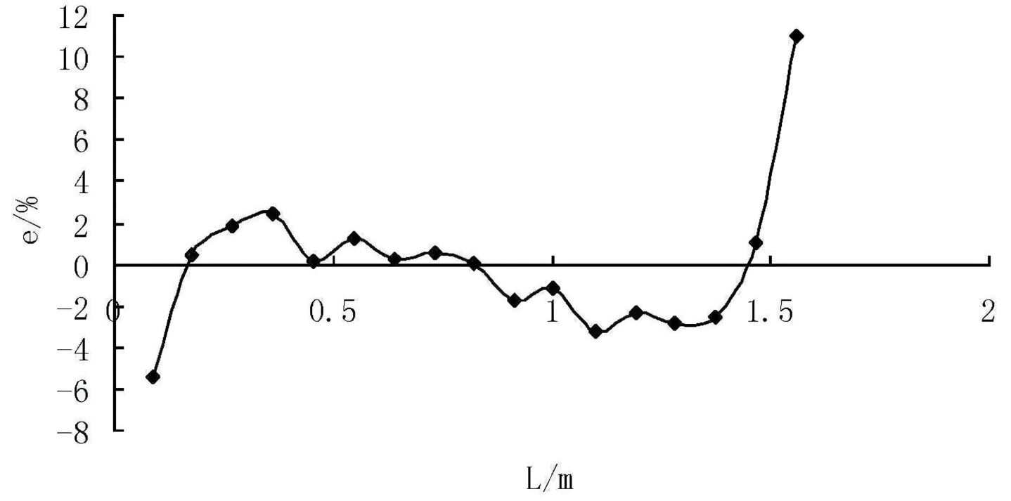
The smaller difference in the maximum and minimum flow rates means the homogenization effect. To illustrate the degree of deviation between the mass flow distribution in the branch and the expected value, we define the mass flow deviation as subtracting the expected value from the mass flow in each branch of the branch bundle, and then dividing by the expected value. As shown in the following equation:
Here, is mass flow deviation, is mass flow in the branch pipe , is expected value of mass flow rate in branch pipe.
The Fig. 7 shows the deviation to expected value of mass flow rate in branch pipes. The trend of the deviation curve is similar to that of the mass flow curve inside the branch pipe bundle. In the branch pipe bundle, the mass flow deviation between the first branch pipe near the large end of the cone pipe and the last branch pipe near the reflux end is significantly greater than that of the other branches. Due to the uneven distribution of velocity and pressure within the main pipe, the mass flow rate distribution of the branch pipe bundle is also very uneven, with a large deviation from the expected value, which cannot meet the basic requirements of uniform slurry distribution in the headbox distributor.
4. Structural Optimization
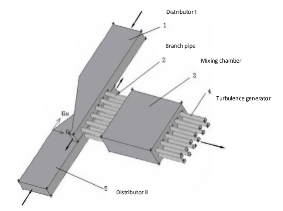
For the rectangle-tapered distributor with branch pipe, the pulp moves forward in a pressure wave, the flow from the total tube to the branch pipe was 90°turning, the vortex cavity was formed at the branch inlet. At the same time, the above numerical simulations have also shown that the velocity, pressure and mass flow distribution of branch pipe in distributor were unevenness, and the exit mass flow distribution were greatly affected by the backflow and the branch length, so it was necessary to optimize the structure of distributor. Using the complementary method, a new type of pulp distributor18) was proposed in this paper, as shown in Fig. 8. Two identical rectangle-tapered distributors with branch pipe I and II were stacked up and down, were symmetrical and unconnected. The function of mixing chamber was to make the branch pipe jet of distributor I and II fully mixed and averaged. The turbulence generator makes the pulp flow into the lip contraction section.
When the distributors I and II still adopt the Baines-type total tube as shown in Fig. 1, the mixing chamber structure was 300 mm in height, 1800 mm in length and 1800 mm in width, and the parameters and boundary conditions of the calculation model were as mentioned in Part 2. The flow velocity contours of pulp in new distributor was shown in Fig. 9. As shown in Fig. 9, at two typical positions of the new type of pulp distributor, namely z = 0.02 and z = –0.022 on the middle surface of the two main pipes, the jet flow process of the pulp entering the mixing chamber from the main pipe through the branch pipe bundle can be well observed. The parallel pipe jet group produces obvious entrainment and interference phenomena between the jet streams, resulting in a tendency for the jet streams to approach each other, which was conducive to the mixing effect between the jets, but also causes the jet streams to gather in the middle after mixing, which to some extent affects the uniform distribution of the pulp after jet mixing.
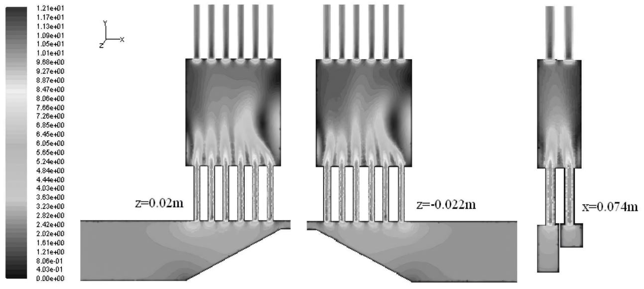
According to the velocity cross-section diagram at x = 0.074 m at the corresponding branch positions of the two main pipe bundles, it can be seen that due to the different mass flow rates of the corresponding branch pipes, one was always larger and the other was smaller, which also produces strong entrainment and interference effects. Moreover, the two jets quickly mix together along the length direction of the mixing chamber, completing complementary averaging and achieving a relatively uniform state near the outlet of the mixing chamber, which was very beneficial for the distribution of the pulp.
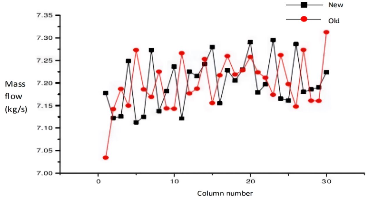
The Fig. 10 was a comparwason of the exit mass flow distribution of new distributor branch pipe with that before optimization. It can be seen that: (1) for all branch pipes, the deviation between the mass flow and the expected value changes from –2.3∼1.57% to –1.21∼1.33%, which reduces the deviation range and improves the uniformity of pulp distribution; (2) the mass flow of branch pipe at inlet end increases from 7.03431 kg·s-1 to 7.17763 kg·s-1, and the deviation from the expected value was 2% lower than that before optimization; (3) the mass flow of branch pipe at backflow end was reduced from 7.31295 kg·s-1 to 7.22399 kg·s-1, and the deviation from the expected value was reduced by 1.23% than that before optimization. Therefore, the flow uniformity of new distributor was improved to a certain extent.
5. Conclusions
The flow field distribution of a rectangule-tapered distributor with Baines-type total tube and branch pipe was numerical simulated by CAD/CAE softwwere, and the flow unevenness phenomenon in the distributor was understood, the main results were as follows:
1) The pulp moves forward in a pressure wave, the flow from the total tube to the branch pipe was 90°turning, the vortex cavity was formed at the branch inlet, the maximum and minimum of branch mass flow were at the backflow end and the inlet end of the total tube respectively, so there was a phenomenon of flow unevenness.
2) The size of backflow and the branch length have great influence on the uniformity of pulp distribution. The larger the backflow and the branch length, the higher the mass flow of branch pipe at inlet end, the lower the mass flow of branch pipe at backflow end. However, Within the range of this study, when the inlet flow rate was 4 m·s-1 and branch diameter was 19.6 mm, the fluctuation of mass flow near the expected value was the smallest when the backflow was 12.5% and the branch length was 150 mm.
3) For the new type of distributor, the average fluctuation of mass flow near the expected value for all branch pipes was optimized by 1.34%, the fluctuation of mass flow near the expected value at inlet end was reduced by 2%, and the fluctuation of mass flow near the expected value at backflow end was reduced by 1.23%, so the uniformity of pulp distribution was improved.
