

1. Introduction
2. Materials and Methods
2.1 Fabrication of BC/CNT composites
2.2 Characterizations of BC/CNT composites
3. Results and Discussion
3.1 Fabrication of BC/CNT composites
3.2 Effect of CTAB on the diffusion of CNTs into a BC cube
3.3 Diffusion distance of BC/CNT composites
3.4 Electrochemical properties of BC/CNT composite as a supercapacitor
3.5 EIS of BC/CNT composite
4. Conclusions
1. Introduction
Unlike plant cellulose, bacterial cellulose (BC) is obtained purely from the culture media without any purification processes since it does not contain any plant-derived contaminants such as lignin, pectin and hemicellulose. BC exhibits excellent physicochemical and mechanical properties including unique nanostructure,1) high water holding capacity,2) high degree of polymerization,3) and high mechanical strength.4) The fibrous network of BC forms well-organized three-dimensional nanofibers, resulting in the formation of hydrogel sheets with substantial surface area and porosity. Especially, BC possesses a porous fibrous structure, acting as an ideal matrix for housing nanoparticles for electrochemical performance.
Supercapacitors are known as electrical double-layer capacitors and present a favorable compromise between batteries and capacitors. Although supercapacitors combine aspects of both capacitors and batteries, unlike batteries, the charge storage in supercapacitors occurs at the interface between the electrode and separator, rather than in the electrode bulk. During charging, ions in the electrolyte migrate to the electrode surface creating a region of high charge density near the interface. In the case of supercapacitors, the electrodes are typically designed to have a high specific surface area for the formation of large interfacial areas in the charging process.5,6,7)
BC/carbon nanotube (CNT) composites were gradually developed in the application of supercapacitors.8,9) Kang et al.10) successfully developed a flexible supercapacitor that exhibited remarkable physical flexibility, high electrochemical properties, and excellent mechanical integrity. This notable accomplishment was attained through a utilization of the unique properties of BC, CNTs, and ionic polymer gel electrolytes. The superior performance of these supercapacitors was attributed to the excellent interfacial quality among the layers, ensuring the retention of performance even under bending cycles.
Here, we verify the effect of an ionic surfactant on the diffusibility of CNTs into the BC networks and the well-dispersed CNT in BC networked structure is applied for a supercapacitive future material. The ionic surfactant adsorbed at the CNT surface tends to repel each other due to the electrostatic repulsion and reduces the aggregation of CNT in the aqueous condition. In addition, the surface adsorption can be confirmed with a zeta potential and the colloidal stability of CNT suspension is investigated with optical absorbance. The diffusion distance of CNT into the BC network is controlled by the concentrations of CNT and ionic surfactant. Especially, the cationic surfactant adsorbed at the CNT and BC fiber surfaces increases the diffusibility of CNT into the BC network by alleviating the aggregations of CNT. Moreover, various electrochemical properties confirm the feasibility of the BC/CNT composite as a supercapacitor proposing optimal compositing conditions for supercapacitor performance.
2. Materials and Methods
2.1 Fabrication of BC/CNT composites
Purified BC cubes (Profood International Corp., Republic of the Philippines) were prepared by heating 4 kg of BC in 2 L deionized water at 60°C under stirring for 60 min, and then rinsing them with deionized water. The process was repeated 8 times to purify the BC cubes completely.
A CNT dispersion solution was prepared by adding CNT (NC7000™ series multi-walled carbon nanotubes, Nanocyl Korea, Republic of Korea) and hexadecyltrimethylammonium bromide (CTAB, ≥ 98%, Sigma-Aldrich, St. Louis, MO, USA) to deionized water and sonicating with an ultrasonic liquid processor (VCX 130, Sonics & Materials, Inc., USA) for 3 min.
The pure BC cubes (15 mm × 15 mm × 15 mm) were immersed into 0.5 wt% of CNT dispersion solution with 0.25, 0.5, 1.0, and 2.0% CTAB, and shaken in the incubator (HB-201SF, KTENG Corp., Republic of Korea) at 25°C and 100 rpm for 24, 48, and 72 h. After finishing the shaking, BC/CNT composites were washed with running deionized water for another 24 h.
BC/CNT composite hydrogels were dried in the oven at 80°C for 1 day, given a load of 2 kg. The dried film was cut into the size of 10 mm × 15 mm for the test of electrochemical performances. BC/CNT supercapacitor was fabricated by attaching a copper tape on each side of BC/CNT composite films for the electrode part.
2.2 Characterizations of BC/CNT composites
The surface of BC cubes was imaged using an inverted fluorescence microscope (CELENA® S, Logos Biosystems, Republic of Korea). The morphological structure of freeze-dried pure BC cubes, BC/CNT composites and BC treated with CTAB samples was imaged using a field-emission scanning electron microscope (FE-SEM, SIGMA, Carl Zeiss, UK). Platinum was sputtered onto the samples at 20 mA for 100 s as a conductive coating for imaging purposes. All samples were imaged by InLens mode. Pure BC cubes and BC/CNT composites were imaged under 2 kV of accelerating voltage and 50 K of magnification, while BC treated with CTAB samples were imaged under 5 kV of accelerating voltage and 10 K of magnification.
The diffusion distance of CNT was measured from the cross-sectional images of each BC/CNT composite hydrogel. Each sample was immersed in O.C.T. Compound (Tissue-Tek®, Sakura Finetek, USA) in a 20 mm × 20 mm × 20 mm silicon mold and frozen by liquid nitrogen gas. The frozen samples were cut to identify the cross-section using a microtome (CM1850, Leica Biosystems, Germany) at -30°C. The cross-section of the BC/CNT composite hydrogels was imaged by an optical camera and the diffusion distance was analyzed with images using the ImageJ program (1.52a NIH, USA).
The zeta potential analysis of BC treated with CTAB was conducted by a zetasizer (Zetasizer Lab, Malvern Instrument, UK). BC cubes were immersed in 0.05, 0.1, 0.2, 0.25, 0.4, 0.5, 1.0, and 2.0% CTAB solution for 1 day. The BC cubes treated with CTAB were dissembled by a homogenizer (HG-15D, SAEHAN LAB, Republic of Korea) at 8,000 rpm.
The CNT aggregation in CNT solutions was imaged using an energy-filtering transmission electron microscope (EF-TEM, LIBRA 120, Carl Zeiss, UK). The CNT solutions were prepared under 0.25, 0.5, 1.0, and 2.0% CTAB at 0.5% CNT and sonicated using an ultrasonic liquid processor for 3 min. The sonicated CNT solutions were dropped on a glow-discharged carbon copper grid and CNT were negatively stained with a 10 µL uranyl acetate solution (1% w/v). After the processing, all samples were imaged under 120 kV of accelerating voltage and 50 K of magnification.
Conductivity was measured using a multimeter (PC7000, Sanwa, Japan), with two points and each point was 5 mm away from the center of the sample. Capacitance was measured after charging for 2 min at a voltage of 0.5 V using a power source. Electrochemical impedance spectroscopy (EIS), cyclic voltammetry (CV), and galvanostatic charge-discharge (GCD) were conducted by PalmSens4 (PalmSens, the Netherlands).
3. Results and Discussion
3.1 Fabrication of BC/CNT composites
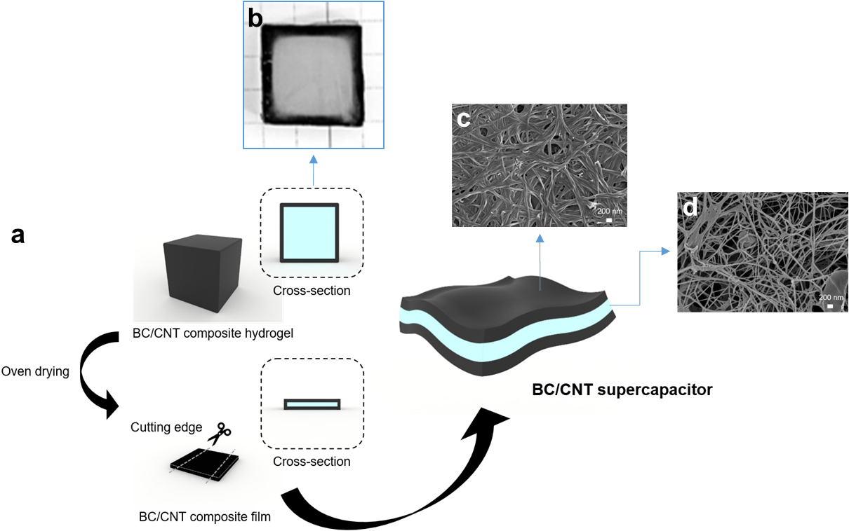
BC/CNT composites were fabricated at different CNT concentrations under the fixed CTAB concentration and at different CTAB concentrations under the fixed CNT concentration by varying the diffusion time. The CNTs are diffused into the hydrogel state of a BC cube spontaneously in the stirring process by the surface modification with cationic surfactant such as CTAB. The CNTs interpenetrate the BC cube and immobilized near the surface due to the high aspect ratio of fibrous structure and entanglement. In addition, CNT bundles diffuse to the inner region of BC cube since the BC networked structure swells after the addition of CTAB. Moreover, CTAB modified CNTs are more diffusible to the hydrophilic minimizing the aggregation of bundles (Fig. 1a). After drying, a BC/CNT composite hydrogel dehydrates and forms a thin film structure where CNT electrodes are separated by a BC layer. The morphological structure of BC/CNT composite showed highly packed CNTs at the surface (Fig. 1c) and porous BC nanofibrous networked structure at the cross-section (Fig. 1d). CNT bundles are a typical feature of aggregated CNTs in the aqueous medium while the BC absorbs water and swells forming space between fibers. Both sides form an electrode with nanofibrillar structure of surface. The BC separates the CNT electrodes safely and keeps the supercapacitor wet for the electrolytes to retain the high mobility. It is a simple process to fabricate a paper-based supercapacitor with CNTs.
3.2 Effect of CTAB on the diffusion of CNTs into a BC cube
The sedimentation test of the CNT solutions also shows the influence of CTAB on the dispersibility of CNT. Fig. 2a presents the 0.5% CNT solution at different CTAB concentrations while Fig. 2b shows the CNT solution after 7 days of sedimentation. In the 0.5% CNT solution, a visible improvement in CNT dispersion was observed with higher concentrations of CTAB. The solution gradually exhibited a darkening tendency, which persisted even after 7 days of sedimentation. Additionally, sedimentation of CNT particles was observed through optical examination.

Fig. 2.
0.5% CNT solutions at different CTAB concentrations (a) immediately after the sonication for 3 min and (b) after storing the solutions for 7 days. TEM images of 0.5% CNT solutions at (c) 0.25%, (d) 0.5%, (e) 1.0%, and (f) 2.0% CTAB. (g) Zeta potential analysis of BC treated with different CTAB concentrations.
The influence of CTAB on the dispersibility of CNT was observed through TEM images of CNT solutions. Fig. 2c-f shows 0.5% CNT solutions at different CTAB concentrations. A significant reduction in CNT aggregation and a decrease in CNT diameter were observed as the CTAB concentration gradually increased (Fig. 2c-f). The surface potential of the BC and CNT was analyzed to confirm the effect of CTAB on the BC surface during the diffusion process. In the case of pure BC, the zeta potential generally represents a negative value.11) The measured zeta potential value of pure BC was determined to be -6.78 mV. In contrast, the zeta potential values were found to be 8.180 mV at 0.25% CTAB, 10.25 mV at 0.5% CTAB, 12.36 mV at 1.0% CTAB, and 26.91 mV at 2.0% CTAB when BC was treated with CTAB solution for 24 h (Fig. 2g).
The results demonstrated that the increase in the CTAB concentration led to the increase in the zeta potential value. This observation showed that CTAB molecules adhered to the BC fibers and modified its surface potential during the diffusion process. It can be inferred that a cationic surfactant of CTAB interacted with the BC surface inducing a positive charge. This enhanced the electrostatic repulsion between BC fibers and thereby facilitated the infiltration of CNT into the BC network.
3.3 Diffusion distance of BC/CNT composites
The diffusion distance was measured through the cross-section of BC/CNT composite for each condition to compare the degree of diffusion. The diffusion distance of BC/CNT composite for each condition can be confirmed through Fig. 3. Fig. 3a shows composites fabricated at 0.05, 0.1, 0.3, and 0.5% CNT with CTAB concentration fixed at 0.2%. Fig. 3a shows cross-section of composite samples diffused for different diffusion times at 0.05, 0.1, 0.3, and 0.5% CNT. Fig. 3b shows the diffusion distance measured from the cross-section of each sample. The diffusion distance of CNT in BC composites exhibited the highest value at 0.1% CNT while it decreased at higher CNT concentrations.
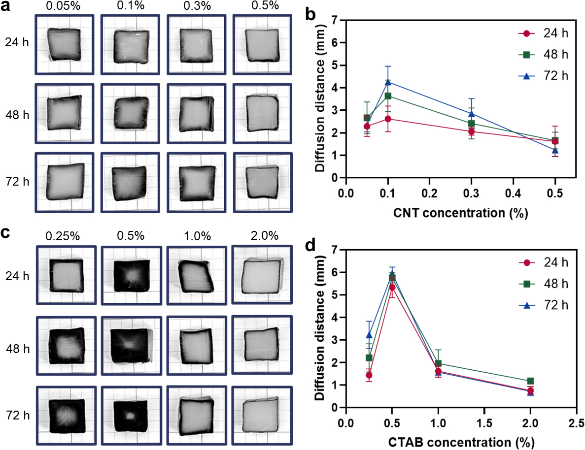
Fig. 3.
Diffusion distance at different CNT and CTAB concentrations. (a) Optical images of samples diffused for different diffusion time and CTAB concentrations : CTAB concentration at 0.2%. (b) Diffusion distance of CNTs of a. (c) Optical images of samples diffused for different time and CTAB concentrations : CNT concentration at 0.5%. (d) Diffusion distance of CNTs of c.
Fig. 3c shows composites fabricated at 0.25, 0.5, 1.0, and 2.0% CTAB fixing the CNT concentration at 0.5% and Fig. 3d shows the diffusion distance measured from the cross-section of each sample. The diffusion distance of CNT showed the highest value at 0.5% CTAB, but it decreased at higher CTAB concentrations inferring optimal conditions for the CNT diffusion in a BC hydrogel.
3.4 Electrochemical properties of BC/CNT composite as a supercapacitor
CNT in the BC/CNT composite serves as a conductive material, so the BC/CNT composite exhibits electrochemical properties. Interestingly, the BC/CNT composite can form EDLC because the BC network layer without CNT acts as a separator while the layer embedding conductive CNTs is an electrode. In this study, the electrochemical properties of BC/CNT composite were investigated to find a feasibility as a supercapacitor.
Conductivity is a crucial parameter of a capacity of material to facilitate current flow. Enhancing the energy storage capacity of a supercapacitor is necessary in designing battery-type materials exhibiting high electrical conductivity.12)Fig. 4a illustrates the variation in conductivity of BC/CNT composite films under different conditions. Fig. 4a shows the conductivity of composites fabricated at 0.25, 0.5, 1.0, and 2.0% CTAB concentrations with the fixed CNT concentration at 0.5%. Specifically, the highest conductivity was shown at 0.5% CTAB, which was similar to the result of diffusion distance. It can be inferred that the quantity of diffused CNT influences the conductivity.
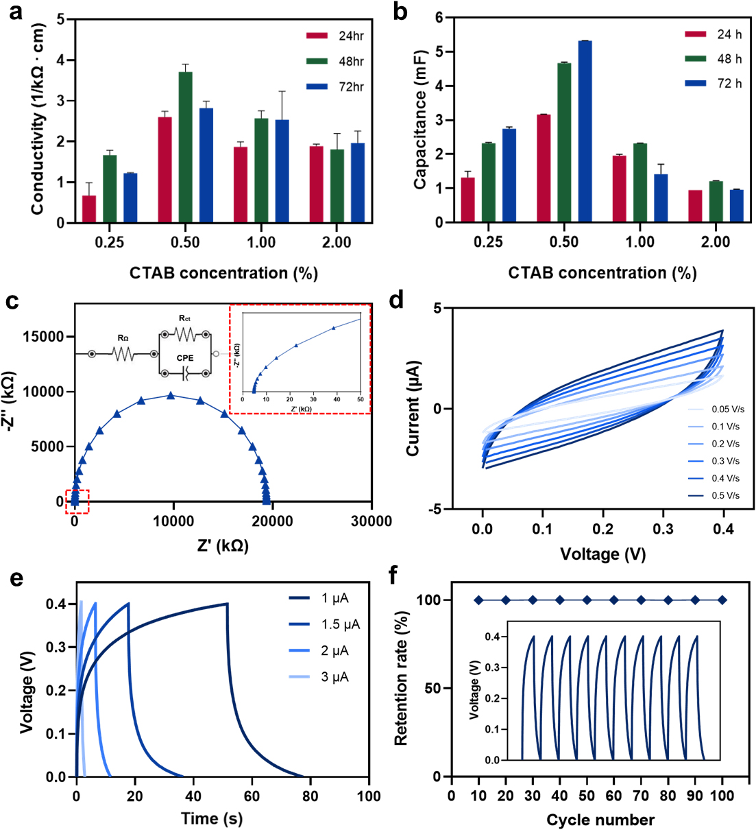
Fig. 4.
Electrochemical properties. (a) Conductivities of composites diffused under 0.25, 0.5, 1.0, and 2.0% CTAB at 0.5% CNT. (b) Capacitances of composites diffused under 0.25, 0.5, 1.0, and 2.0% CTAB at 0.5% CNT. (c) Capacitances of composites diffused under 0.25, 0.5, 1.0, and 2.0% CTAB at 0.5% CNT. (c) Nyquist plot of BC/CNT composite under 0.5% CNT and 0.5% CTAB for 72 h diffusion. (d) CV curves of BC/CNT composite under 0.5% CNT and 0.5% CTAB for 72 h diffusion. The scan rate ranges from 0.05 to 0.5 V/s. (e) GCD curves of BC/CNT composite under 0.5% CNT and 0.5% CTAB for 72 h diffusion. The current values ranges from 1 to 3 uA. (f) Cycle stability test from GCD curves of BC/CNT composite under 0.5% CNT and 0.5% CTAB for 72 h diffusion. The total test was examined for 100 cycles.
Capacitance is the measure of an ability to store an electrical charge. It is necessary to show good electro-capacitive performance to improve the energy-storage capability of a supercapacitor.12)Fig. 4b presents the variations in capacitance of BC/CNT composites under different conditions. The capacitance measurements were conducted after applying a charging voltage of 0.5 V for 2 min using a power source.
Fig. 4b shows the capacitance of composites fabricated at 0.25, 0.5, 1.0, and 2.0% CTAB concentrations with the fixed CNT concentration at 0.5%. Due to the high CNT concentration, the highest capacitance was observed at 0.5% CTAB. However, this highest capacitance value exhibited a substantially lower level when compared to the values reported in other references.13,14) Nevertheless, based on the capacitance characteristics of the supercapacitor, it can be concluded that the composite with high capacitance is the most affordable for supercapacitor applications. Accordingly, the composite diffused for 72 h at 0.5% CNT and 0.5% CTAB demonstrated the most suitable characteristics as a supercapacitor, representing an optimized sample. For the reason, all subsequent electrochemical data measurements were performed with the composite diffused for 72 h at 0.5% CNT and 0.5% CTAB.
3.5 EIS of BC/CNT composite
EIS has been used widely to analyze the performance of electrical energy storage devices. Nyquist plot, one of the EIS, represents negative of the imaginary part (-Z") versus the real part of the complex resistance (Z') of individual electrodes or electrochemical cells. It consists of a semicircle at high frequencies showing a nonvertical line at intermediate frequencies and a nearly vertical line at low frequencies.15) The obtained impedance values can be effectively analyzed by fitting the EIS spectra to Randles circuit model. The Randles circuit model consists of various electrical circuit elements including resistors, capacitors, and inductors. In the case of supercapacitors, an electrical double-layer has capacitive characteristics between the electrode and the separator. However, these characteristics deviate from those of an ideal supercapacitor due to factors such as surface roughness, leakage capacitance, and nonuniform distribution. To account for this nonideal behavior, the concept of a constant phase element (CPE) is introduced in the modeling of the electrical double-layer. CPE helps compensate for the nonideal behavior and provides an accurate representation of the performance within the Randles circuit model.16)Fig. 4c shows Randles circuit model suitable for the composite. It consists of bulk resistance (RΩ), charge-transfer resistance (Rct), and a CPE. The Nyquist plot shown in Fig. 4c was fitted with the Randles circuit. In this plot, RΩ shifts the starting point of the semicircle to higher Z' values, which is 4.756 kΩ. At the end of this semicircle intercept on the x-axis, which is 19,374.94 kΩ, can be interpreted as the internal resistance. It represents the sum of bulk resistance and charge-transfer resistance, therefore the diameter of the semicircle shows the charge-transfer resistance, which is 19,370.184 kΩ. However, it was observed that these resistance values exhibited significantly higher than those from reported in other supercapacitor researches with conductive electrodes due to the existence of the nonconductive layer in the middle of the BC/CNT composite.14,17)
CV is a widely used technique in the characterization of electrical energy storage devices. It involves sweeping the potential at the working electrode back and forth is swept back and forth within a given potential window at a constant scan rate. The resulting current is plotted against the corresponding potential values. For an ideal supercapacitor, the CV curves have a shape close to rectangular with an insignificant dependence of the differential capacitance on the potential of the electrodes.18,19,20) At high scan rates, CV curves appear as a leaf-like shape. For all supercapacitors, sufficiently high scan rates lead to these leaf-like CV curves.5) In Fig. 4d, it shows CV curves of BC/CNT composites at different scan rates from 0.05 to 0.5 V/s. The shape of all curves exhibits leaf-like shape. As the scan rate increased, the peak current density increases but the shape is maintained with only slight deviation, which shows that this composite possesses good capacitive behavior.
GCD tests are often used to evaluate energy storage systems and materials.21) In the case of an ideal supercapacitor, the charge and discharge plots are symmetrical and maintain a constant slope throughout the entire process.5)Fig. 4e shows GCD curves of BC/CNT composite at different currents ranging from 1 to 3 µA. The GCD curves are similar in shape between 0 and 0.4 V, but shows the non-linearity of the charge and discharge curves. It means that the energy storage during charging was not completely discharged.22) With an increase of the current value from 1 to 3 µA, it can be attributed to progressively less efficient infiltration of ions into electrodes at higher current values. On the other hand, the ions have sufficient time to gain access to diffuse from the electrolyte deep into electrodes at the lower current values.23)
The cycling stability of the electrode material for supercapacitors is another important parameter for energy source material in high power and energy applications. Cycling stability test was examined by GCD measurements for 100 cycles. Fig. 4f shows the retention rate of potential based on GCD curves at the 1 µA current value. The retention rate was calculated by measuring the potential value of every 10th cycle based on the potential value of the first cycle. The retention rate was maintained over 99.94% for the 100 cycles indicating good cycling stability as a supercapacitor. In terms of practical applications, the cycle is needed to increase up to 10,000 to ensure stable electrochemical performances of the device. In addition, the excellent mechanical properties of the BC/CNT composites should be verified to highlight their potential applications in flexible and wearable devices.
4. Conclusions
BC/CNT composites were fabricated using a diffusion method, which allowed the 3D network structure of BC to be preserved. In the fabrication process of BC/CNT composites, the diffusion distance of CNT into BC was varied depending on the ratio of CNT to CTAB. Zeta potential showed the positively charged surface of BC fibers due to the adsorption of CTAB. It increased the electrostatic repulsion between the BC fibers facilitating the diffusion of CNT into the BC network. Moreover, CTAB improved the dispersibility of CNT by alleviating the aggregations of CNT. The electrochemical properties confirmed the feasibility of the BC/CNT composite as a supercapacitor. It is expected that the BC/CNT composites can be applied for the wearable or sensing devices in the future. Due to the 3D networked structure of BC, the BC/CNT composite fabricated through the diffusion method possesses remarkable mechanical properties, but further investigations are needed to enhance the electrochemical performance.
