

1. Introduction
Paper manufacturing industry is an important basic raw material industry in China’s national economy. In the process of papermaking, the energy consumption by drying accounts for over 50% of the total energy consumption of paper machine. Thus, one of the main approaches to reduce the energy consumed by drying is to reduce thermal resistance and improve the drying efficiency of dryer. In conventional dryer, vapor condenses to release heat and form condensate water. When the dryer rotates at a high speed, the condensate water cannot be discharged in time, forming a condensate water ring and thereby increasing the thermal resistance of the dryer for heat transfer.1)
In order to reduce the thermal resistance caused by the condensate water layer in traditional dryer and improve the drying efficiency, Choi et al. proposed a multi-channel interlayer dryer.2,3) Its working principle is as follows: vapor enters the inner cylinder of the dryer and driven by steam pressure, reaches the other end of the dryer from the inlet end and then enters the interlayer channel, where condensation and heat transfer are completed. Dong et al.,5,6) based on the interlayer dryer proposed by Choi et al., developed a new multi-channel dryer which has a similar structure to the interlayer multi-channel dryer and whose inner wall is evenly distributed with several rectangular channels along the circumferential direction. Its working principle is: after passing through the air inlet, vapor directly enters the rectangular channels and condenses and transfers heat in the channels; the condensate water generated during the heat exchange is pushed by the subsequent vapor and thus discharged from the channels. To better discharge the condensate water, a certain angle can be set between the channel and the shaft, which solves the problem of condensate water ring and reduces the thermal resistance of dryer for transferring heat.
The channels of the multi-channel dryer have the same structure and similar heat transfer behaviors, so Choi et al. and Shin et al. used a rectangular channel to measure its average heat transfer coefficient.2-4) The results showed that the average heat transfer coefficient of multi-channel interlayer dryer could reach 15,000 W/(m2·K), which was 7-20 times that of the condensation heart transfer coefficient of a traditional dryer. Yan et al. and Yang et al.,7-9) through the experimental research, found that the mean heat transfer coefficient of a single rectangular channel was 8,000-24,000 W/(m2·K).
The experimental data of Choi and Yan et al. were obtained under the static condition of rectangular channel. However, in a practical situation, the dryer works under a rotating state. Besides, the multi-channel condensation heat transfer belongs to the single-wall condensation heat transfer. Though there are many international and domestic researches on the heat transfer of rectangular channels in rotating state,10-12) few are about single wall heat transfer.
Therefore, a multi-channel dryer rotating test bench was designed in this paper to further study the variation of steam condensation heat coefficient and flow pressure drop in single-wall rectangular heat transfer channel at different rotational speeds and steam mass velocities, which provided some experimental data for the design of multi-channel dryer.
2. Design Principle
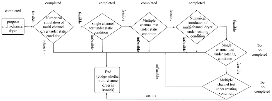
The multi-channel dryer is currently in the experimental research stage, and its design principle is shown in Fig. 1. Previous experiments have been carried out on the condensation heat transfer coefficient of rectangular channels in multi-channel dryer under static conditions. To further improve the experimental data of condensation and heat transfer of a single and multiple channels under a rotating state, this paper built a rotating test bench so as to provide a basis for the further study of the multi-channel dryer.
The schematic diagram of the multi-channel dryer rotating test bench is shown in Fig. 2. The test bench mainly includes a rotary device, a steam circulation system, and a coolant circulation system, among which the rotary device is used to drive the test piece to simulate the rotating state of actual dryer, the steam circulation system is used to generate steam and realize the recycling of steam, and the coolant circulation system is used to simulate a wet paper web.
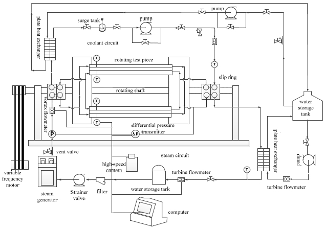
The rectangular channel component is fixed on the rotating disk by T-bolts and rotates with the disk. The vapor generated by the steam generator enters the channel through a vapor-liquid electric slip ring; after passing through the channel, the vapor is cooled by the plate heat exchanger and then enters the water storage tank again. Cooling water is used as a coolant in this test. The cooling water enters the channel through the vapor-liquid electric slip ring; after the cooling water flows through the channel, it is cooled by a plate heat exchanger, thereby realizing the circulation of cooling water. The power to rotate is provided by the variable frequency motor in the rotary device. The data of parameters during the test are obtained through the temperature sensor, the differential pressure transmitter, the pressure transmitter, and the flowmeter.
3. Design and Calculation of Rotary Device
3.1 Components of rotary device
The rotary device is mainly composed of a rotating disk, a rectangular channel component, a transmission shaft, a main frame, a fixed snap ring, a vapor-liquid electric slip ring, a thermal resistance gathering module, a side frame, a thermal resistance, a flowmeter, a tensioning gear, and a transmission system, as shown in Fig. 3. The rotating radius of the test bench is 800 mm; the length of the rectangular channel is 1,100 mm; and the rotational speed is set to 140-318 r/min.
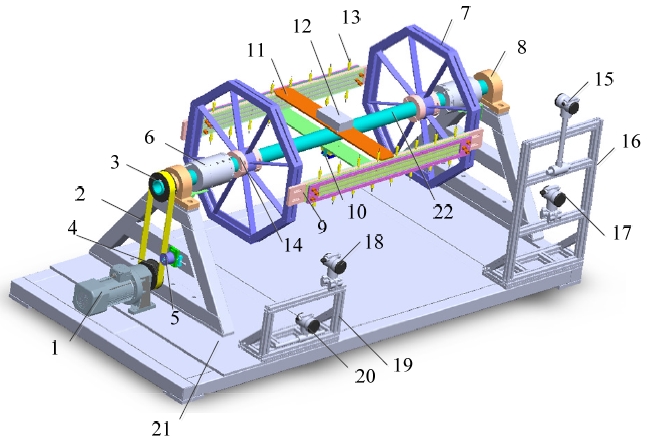
Fig. 3.
Structure drawing of rotary device. 1-Variable frequency motor, 2-Synchronous belt, 3-Big belt wheel, 4-Small belt wheel, 5-Tensioning gear, 6-Vapor-liquid electric slip ring, 7-Disk, 8-Bearing, 9-Channel component, 10-Power module, 11-Support plate, 12-Thermal resistance gathering module, 13-Thermal resistance, 14-Fixed snap ring, 15-Vortex shedding flowmeter, 16-Side frame 1, 17-Pressure transmitter, 18-Differential pressure transmitter, 19-Side frame 2, 20-Turbine flowmeter, 21-Underframe, 22-Main shaft.
3.2 Channel component
The channel component is the test piece of this study which is used to study the changes of the temperature and flow pattern of steam in the channel. The channel component is mainly composed of channel, gasket, PC board, PC board gland, and coolant channel cover plate, as shown in Figs. 4 and 5. Since the steam condensation flow pattern in the channel needs to be captured by high-speed camera, the pressure plate on the side of steam channel is made of transparent PC plate. 8 thermal resistances are distributed on the upper and lower sides of the channel to detect the changes in steam and wall temperatures.
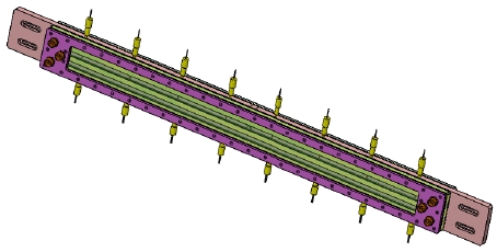
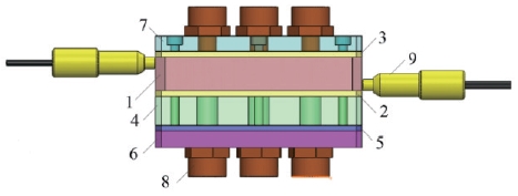
Fig. 5.
Structure diagram of channel component. 1-Retangular channel, 2-Gasket 1, 3-Gasket 2, 4-PC board, 5-Gasket 3, 6-PC board gland, 7-Coolant channel coverplate, 8-Pipe joint, 9-Thermocouple.
During rotation, the channel bends owing to centrifugation, which affects the reliability of the equipment. There are two engineering methods to calculate the deformation of the structure of the channel under the centrifugal force field, i.e., the quadratic element method and the finite element method. The quadratic element method is to simplify the channel into a plane stress problem to solve. Thus, the finite element method is adopted in this paper. When the rotational speed is the highest, the centrifugal force is the largest. As both ends of the channel are fixed, the maximum centrifugal force is evenly applied on the channel plane to perform simulation. The channel is made of aluminum alloy, whose material properties are listed in Table 1.
Table 1.
Structural material properties of channel
| Material | Density/kg·m-3 | Elasticity modulus/GPa | Poisson’s ratio | Fatigue limit/MPa |
|---|---|---|---|---|
| Aluminum alloy | 2,770 | 71 | 0.33 | 280 |
The simulation results are shown in Fig. 6. The results show that the deformation of the middle part of the channel is the largest, reaching 6.384 mm, and the maximum stress of the channel is smaller than the yield stress. The allowable deflection of channel is
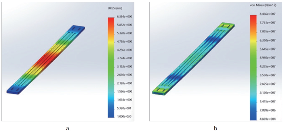
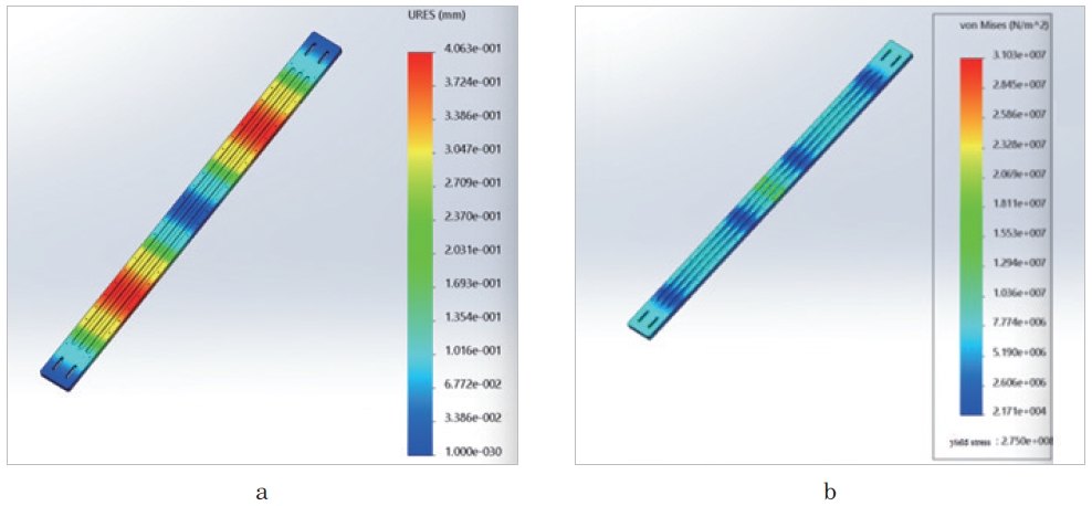
where l is the total length of the channel, so the maximum allowable deformation of the channel is 2.2 mm. As the stress deformation at the middle of the channel is greater than 2.2 mm, to reduce the deformation, a group of support plates are installed at the middle of the channel to increase its strength. Simulation analysis is conducted on the improved channel; the results are shown in Fig. 7. The results show that the deformation of the channel decreases significantly and the maximum deformation is 0.4 mm, which is less than the allowable deflection. Therefore, the improved channel is adopted in this paper.
3.3 Frame of the test bench
The frame of the rotating test bench is composed of a main frame and two side frames. The main frame, which is 2,900 mm in length, 1,350 mm in width, and 665 mm in height, is used to support the rotating shaft and fix the motor. The two trapezoidal side support plates of the main frame with large strength and small mass are made of 80×80 mm box iron. The two side frames, which are made of 40×40 mm square tube, are used to fix the vortex flowmeter, the turbine flowmeter, the pressure transmitter, and the differential pressure transmitter.
3.4 Shaft system
The shaft system used in the test mainly consists of a main shaft, a rolling bearing, a vapor-liquid electric slip ring, a disk, and a fixed snap ring, among which the main shaft is driven by a variable-frequency and variable-speed motor whose maximum speed is 318 r/min.
The inner diameter of the main shaft is 58 mm, the outer diameter is 80 mm, and the length is 2,463 mm. The vapor-liquid electric slip ring used is a Slip Ring which can withstand a steam temperature of 150°C and a pressure of 0.5 MPa.
The disk, whose inner diameter is 80 mm and wall thickness is 30 mm, is welded into an octagonal shape with 63×63 mm box iron. Eight ribs that are 4 mm in thickness are used to increase the strength of the disk. The disk is fixed on the shaft through connections. To prevent the disk from moving along the shaft, a fixed snap ring is installed on both sides of the disk respectively. The snap ring consists of two half rings which are fixed on the shaft by bolts. There are 9 mm wide and 285 mm long rectangular holes on the sides of the disk’s box iron, which are used to adjust the inclination angle between the channel and the main shaft. The maximum inclination angle is 10°.
3.5 Drive system
In this test, the influences of different rotational speeds on heat transfer coefficient of the rectangular channel need to be studied, so a variable-frequency and variable-speed motor is used to provide power for the main shaft. By adjusting the frequency converter, the different rotational speeds can be realized.
The total mass of the rotating disk, channel component, and support plate is about 25 kg, 21 kg, and 2.7 kg, respectively.
According to the theoretical mechanical formula13):
Where m is the mass of support plate (kg) and R is the turning radius (m).
Thus, the rotational inertia of the two support plate is J1=0.96 kg·m2, and the rotational inertia of the two channel components is J2=6.72 kg·m2.
According to the theoretical mechanical formula13):
The rotational inertial of the disk is J3=4 kg·m2. Thus, the total rotational inertial is J=11.68 kg·m2.
Let the time from the motor starts to the disk rotates uniformly be 15 s, then the maximum speed of smooth rotation is 318 r/min. Thus, the angular acceleration when the disk reaches the maximum rotational speed is α=2.2 rad/s2, and the moment the disk needs during the acceleration is M=25.7 N·m. During the uniform rotation of the disk, the main moment is the friction moment between the main shaft and the rolling bearing. Since the friction coefficient of the rolling bearing is only 0.0015, the friction moment is ignored. The kinetic energy required by the disk to accelerate from zero to a uniform speed is:
Where ω is the angular velocity of the disk.
Through the Eq. 3,, the kinetic energy is E=6,359.76 J. So the amount of power required by the disk during the acceleration is P=424 W.
Therefore, the power that the motor needs to provide is P2 = p + J4α1.
Where J4 is the equivalent rotational inertia of motor and α1 is the angular acceleration of motor.
To sum up, the variable frequency motor used in this test is an F1500Y22L3H motor whose power is 1,500 W and the reduction ratio is 3.
The motor is installed on the base board to reduce vibration and improve the stability to the test bench during rotation. Generally, the belt or synchronous belt wheel is used in drive system. The synchronous belt wheel is adopted in our test, because its accurate transmission ration and low noise are conducive to realize the accurate control of the rotational speed of the disk. The transmission ratio of the synchronous belt wheel is 1:1. According to the speed of the small belt wheel and the power of the motor, the model of the synchronous cog belt is S8M.14)
The inner diameter of the big belt wheel is the same as the outer diameter of the main shaft, and the inner diameter of the small belt is equal to the outer diameter of the motor’s output shaft. Thus, the model of the big belt wheel is S8M400-60-A-N-d80, the belt width is 40 mm; the number of teeth is 60; the inner diameter is 80 mm. The model of the small belt wheel is S8M400-60-A-N-d32; the belt width is 40 mm; the number of teeth is 60; the inner diameter is 32 mm.
After running for a period of time, the synchronous cog belt will become loose due to permanent deformation, resulting in the decline of the initial tension. Therefore, it is necessary to add a tensioning gear to the transmission device to ensure the transmission ca pacity.
4. Modal Analysis of Rotary Device
Resonance, which will affect the stability, accuracy and service life of the test device, may occur in the actual rotating process. To study the resonant speed of the test bench and avoid resonance, the modal analysis is conducted on the test bench. Modal characteristics are the inherent vibration characteristics of a mechanical structure. Each mechanical structure has its corresponding frequency and modal shape.
The rotary device is simplified and its relevant parameters are input into ANSYS software. The channel and supporting plate are made of aluminum alloy, and other parts are made of structural steel. The material properties of the rotary device are presented in Table 2. The four bottom corners of the test bench are set as fixed ends onto which gravity acceleration is applied to perform modal simulation. The modal information of the first 6 stages is extracted for comparative analysis. The modal frequencies and shapes of the first 6 stages are listed in Table 3, and the corresponding calculation results are shown in Fig. 8.
Table 2.
Material properties of experimental devices
| Material | Density/kg·m-3 | Elasticity modulus/GPa | Poisson’s ratio | Fatigue limit/MPa |
|---|---|---|---|---|
| Aluminum alloy | 2,770 | 71 | 0.33 | 280 |
| Structural steel | 7,850 | 200 | 0.3 | 250 |
Table 3.
The modal frequencies of the test bench of the first 6 stages
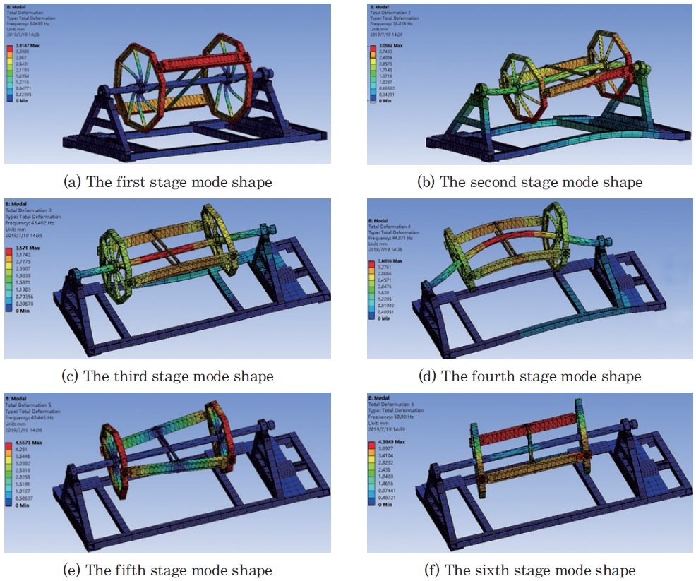
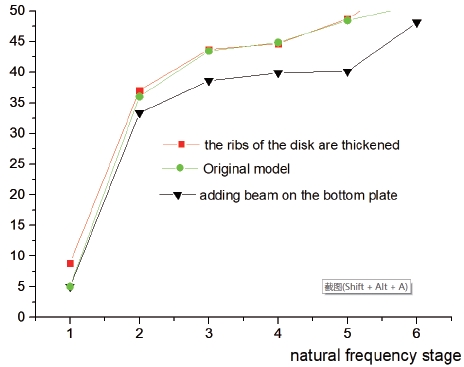
It can be known from the modal shapes of the first 6 stages that the frequency at the first stage modal is 5.0489 Hz. The speed of resonance is about 300 r/min, which is close to the rotational speed of the test device (318 r/min). In order to avoid resonance, the hardness, mass, and external size of the test device need to be altered. When the test device deforms, elasticity restores it and mass affects its acceleration. Elasticity is mainly related to size and hardness. When the size of the test device is constant, the device with larger hardness is higher in frequency, and the device with larger mass is lower in frequency. To increase the natural frequency of the test device, the test device is improved in two ways. First, a beam is added at the middle of the base plate; second, the ribs of the disk are thickened from 4 mm to 6 mm. The calculation results of the modal frequency before and after improvement are shown in Fig. 9. The results show that adding beam on the bottom plate has little influence on the natural frequency of the first stage; with the increase of stages, the natural frequency is generally lower than that before the change. Thickening the ribs of disk has increased the natural frequency of the first stage; the natural frequencies of the second to the fifth stages are close to those before the improvement. The maximum rotational speed of the test device is 318 r/min, so the natural frequency of the first stage has a large resonance impact on the test device. The resonant rotational speed after the disk is improved is quite different from the maximum rotational speed of the test device, thereby avoiding the occurrence of resonance.
5. Conclusions
This paper developed a rotating test bench for multi-channel dryer which is mainly composed of a rotary device, a vapor circulation system, and a coolant circulation system. Finite element numerical simulation was carried out on the frame and channel components respectively. The simulation results showed when the thickness of the disk rib was 4 mm, the resonance speed of the test bench was 300 r/min, which was close to the designed rotating speed (318 r/min) of the test bench. Therefore, the thickness of the disk rib should not be 4 mm. When the thickness of the disk rib was 6 mm, the resonance speed of the test bench was 540 r/min, which was much higher than the designed speed; thus, the test bench could operate reliably at the speed of 318 r/min without resonance. By adding support plates between the channel components, the strength and rigidity of the channel components were improved. So the rotating diameter of the test bench could reach 800 mm, and the rotating speed could reach 318 r/min. The simulation results also showed that the test bench was able to meet the design requirements. This paper provides some useful reference for the design and construction of multi-channel dryer test bench.
