

1. Introduction
Nanofibrillated cellulose (NFC) has gained much attention and interest of scientists and researchers because they are biodegradable, renewable, environmentally friendly and abundantly available almost everywhere in the world. There are many research papers concerning the application of nanocellulose in the area such as pharmaceutical, cosmetics, bio-composite, paper coating and others 1-4).
Missoum et al.5) have used SEM, FE-SEM, AFM, TEM and other methods to determine the morphology of nano-size fibers. Many studies suggested that nanofibrillated cellulose has at least one dimension under 100 nm. However, according to Siró and Plackett6), nanofibers have a wide variety of widths that could be from 5 to 120 nm. Recently, Kolakovic7) also noted that nanofibrillated cellulose from different cellulose sources could have width size ranging from 3 to 120 nm.
The crystallinity index, degree of polymerization (DP) and alpha cellulose content are all related to the strength properties of cellulose materials. Researchers have discussed the decreased crystallinity indices and sizes of nanofibrillated cellulose8-10). For the crystallinity index in percent, decrease of 5 to 7 point compared to the starting materials has been widely agreed.
The CED (cupriethylene diamine) viscosity or degree of polymerization is also one of the important factors that contribute to the strength properties of materials. From Seo et. al.11), a lower degree of polymerization means lower strength properties of the cellulose materials. Researchers have been concerned that nanofibrillated cellulose produced by mechanical methods could lead to decrease in DP and viscosity. Zimmermann et. al.12) mentioned in detail that nanofibrillated cellulose materials had DP decreases between 15-63%.
In this study, the effect of electron beam treatment on cotton linter for producing cotton linter nanofibrillated cellulose (NFC) was investigated. It was known that the electron beam irradiation on cellulose fibers caused to decrease cellulose molecular weight, strength properties, thermal decomposition temperature, and crystallinity11). Therefore, the electron beam irradiation on the cotton linter may lead to an energy saving way for preparing NFC. In addition, the effects of grinding and electron beam irradiation on the alpha cellulose contents, fiber morphology, CED viscosities and crystallinity indices were investigated. Films of cotton-NFC were produced for the evaluation of their mechanical properties.
2. Materials and methods
2.1 Materials
The cotton linter for the study was donated by KOMSCO (Korea Minting and Security Printing & ID Card Operating Corp.). Three different types of pre-treatment of the cotton linter were used including the cotton linter control sample, and 10 and 100 kGy electron beam treated samples (Table 1). Electron beams were applied to the samples at the facility of EB Tech Co. located in Daejun, Korea. The electron accelerator of ELV-4 type manufactured by EB Tech Co. was used for the irradiation with 1.0 MeV of energy.
2.2 Methods
2.2.1 Electron beam treatment and sample preparation
The cotton linter control and 10 kGy samples were too tough to be ground, and thereby, pre-treated by a valley beater until freeness of 100 CSF was reached before being ground by the Super Masscolloider (Masuko Sangyo Co. Ltd., Japan)13). The cotton linter treated with electron beam energy of 100 kGy was disintegrated without the valley beater treatment. The samples were diluted to a consistency of around 1-1.3% before being ground by a Super Masscolloider. The cellulose materials were ground at 2000 rpm at an input current of 2.0 A. Many samples of different passes were prepared, and when most of the sample fibril width became under 100 nm, the sample was used as NFC and the number of passes recorded were used as the energy to make NFC.
2.2.2 Nanofibrillated cellulose morphology
An ITplus optical microscope (Sometech Co., Ltd., Korea) and FE-SEM (field emission scanning electron microscope) were used for determining the morphology of the fibers. Fifty fibers were randomly measured to analyze the widths of the fibers according to the researchers14). An x-ray diffractometer (XPERT-PRO) was used to measure the crystallinity of the raw materials and NFC samples. The measurements were carried out over a range of 3° to 40° with a step size of 0.1°. The XRD was operated at 40 kV and 30 mA.
2.2.3 Property measurement
Alpha cellulose content, CED viscosity, crystallinity index, and tensile strength of the samples were measured according to the methods described in Table 2. Films from different cotton linter NFC sources were produced on a 12 x 12 cm glass mold for tensile strength testing. The pre-calculated amount of the vacuumed NFC solution for making 30g/m2 basis weight film was poured over the flat glass, and air-dried to make NFC film. Transparent films were prepared and their mechanical properties were measured according to the standard methods.
3. Results and discussion
3.1 Morphology of the nanofibrillated cellulose
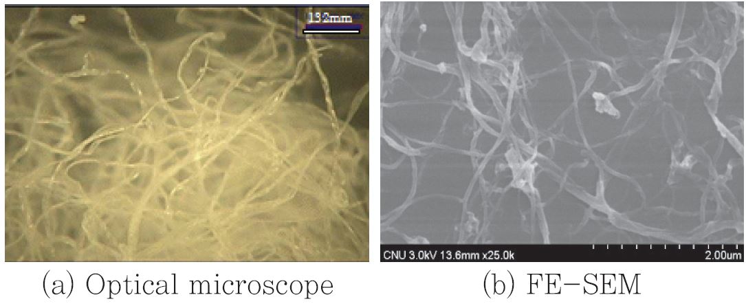
Before grinding, cotton fibers had widths of approximately 14 μm. Fig. 1 showed that the morphology of the fibers changed from micro to nano size due to the grinding process, and they were observed by using a optical microscope and FESEM, respectively. The width of NFC from Cotton LC was in the range of 30-70 nm. We estimated that the cotton linter could be turned into NFC by 21 passes through the Super Masscolloider.
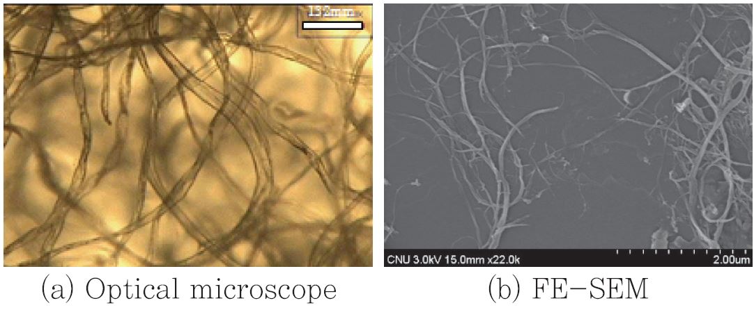
Cotton linter subjected to the 10 kGy electron beam treatment were ground to nano-sized fibrillated cellulose materials by 19 passes of the Super Masscolloider. The fiber morphology change was shown in Fig. 2. The width of the NFC from Cotton L10 was in the range of 30-70 nm, again.
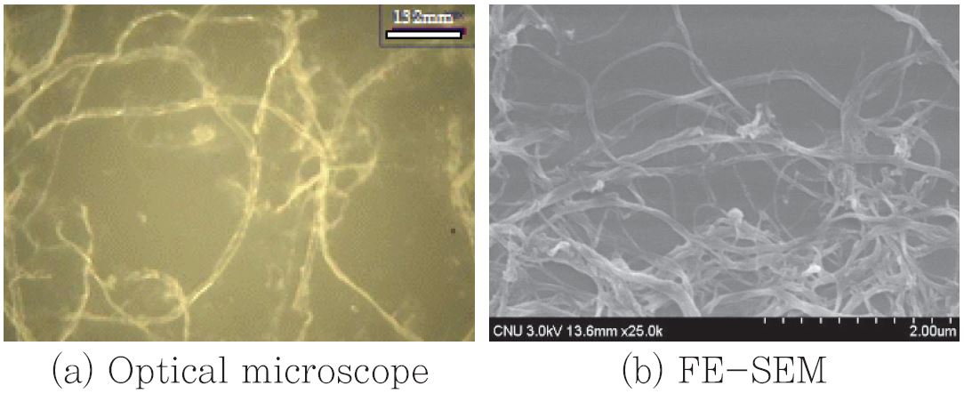
In the case of the 100 kGy treated cotton linter, it was not necessary to pretreat the cotton linter with the valley beater. The Cotton L100 was disintegrated and then transferred to the grinder for NFC production. The final fiber width of the NFC from the Cotton L100 was in the range of 50-70 nm.
The Cotton L100 were a lot easier to make NFC (15 time passes of the Super Masscolloider) and faster to convert from micro size to nanofibrillated materials. The results indicate that the electron beam treated cotton linters were much easier to make NFC. Table 3 showed how many passes were needed through the Super Masscolloider to convert cotton linter materials to NFCs.
Table 3
Alpha cellulose contents and viscosities
3.2 Alpha cellulose, viscosity and crystallinity index
Table 3 shows the results of the alpha cellulose, viscosity and crystallinity index of the cotton linter. The alpha cellulose content of the samples were decreased due to the grinding process. For Cotton LC, the alpha cellulose content dropped by only two units due to grinding; however, those of the 10 kGy (Cotton L10) and the 100 kGy (Cotton L100) treated samples showed large decreases. The alpha cellulose content of the cotton L100 showed a sharply drop from 61.7% to 28.5%, a 70% lower than the starting material by grinding process. It turned out that the grinding process for NFC preparation caused remarkable decrease of alpha cellulose content for the electron beam treated samples, and caused their ground samples to be dissolved effectively in the 17.5% NaOH solution. This is because the cellulose that was not dissolved in 17.5% NaOH solution, was measured as alpha cellulose.
The viscosity was also decreased by the NFC grinding process but in different way. The viscosity of the Cotton LC sample dropped largely by the grinding process, but those of the electron beam treated samples were minimal. We think that the grinding process for high molecular weight materials such as Cotton LC, may consume more energy to lower the molecular weight while for low molecular weight materials such as electron beam treated materials, consume more energy for fibril separation.
The crystallinity indices of the NFCs were decreased due to the grinding process and electron beam treatment. The cotton linter initially had high crystallinity index (82.5%). The electron beam irradiation to the cotton linter lowered the index largely for Cotton L100 case. The grinding process using the Super Masscolloider caused further drop of the crystallinity of all samples by 3-5 points. The 100 kGy electron beam irradiation combined with grinding for preparation of NFC caused the cotton linter a total of 17% drop from its original crystallinity index.
3.3 Strength properties of NFC films
Table 4 shows the strength properties of the NFC films produced by the casting method. The tensile strength and the Young’s modulus of each sample from cotton linter were not largely different, but showed fluctuations. Cotton L20-NFC was added for adding more information. It was expected that Cotton L100-NFC sample, which had the lowest CED viscosity or the lowest DP, might give the lowest tensile properties but did not. In the contrary, The Cotton L100-NFC sample gave the highest Young’s modulus and stress at peak of all. It is hard to explain the results because low DP sample did not lower the tensile strength property. One possible explanation for this behavior is as followed. The NFCs used for film samples were strong enough not to break in this tensile test even though electron beam treatment and grinding process had been applied to them. If that was the case, the film broke in tensile test only when the bonding between NFCs were broken. The bonding between NFCs might not be much different between samples because they were grinded to the NFC in similar dimension and shape. Therefore, significant tensile strength difference might not be shown in the table. The NFC samples gave high Young’s modulus in the table compared to paper materials. The Cotton L10 sample gave the lowest tensile properties of all, which might come from variations in film preparation.
Table 4
Tensile strength of the film samples prepared with the cotton linters-NFC samples
3.4 Thermogravimetric analysis (TGA)
Thermal decomposition temperature of raw cellulose materials were around 360-370oC in Table 5. Due to electron beam treatment, the thermal degradation temperature of cotton linters decreased from 369 to 360oC, which was 9oC difference. Thermal degradation temperature of Cotton L was lowered from 369oC initially to 350oC for its NFC by the grinding treatment, which was 19oC difference. That means that the grinding treatment was more effective to decrease the cellulose degradation temperature than the electron beam treatment up to 100 kGy.
Table 5
Thermal decomposition temperature of the electron beam irradiated cotton linters and their NFCs
| Thermal decomposition temperature. oC | ||
|---|---|---|
| Samples | Raw cellulose | NFC |
| Cotton L | 369 | 350 |
| Cotton L-10 | 366 | 349 |
| Cotton L-20 | 366 | 348 |
| Cotton L-100 | 360 | 345 |
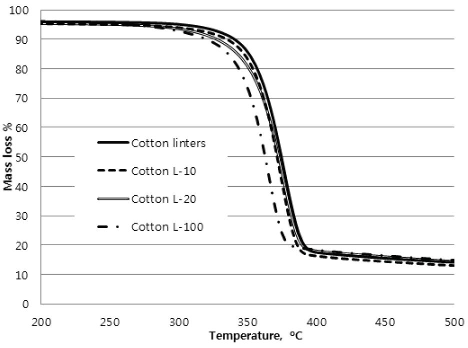
Fig. 4 shows mass loss curves of TGA for cotton linter and its NFC, respectively. For cotton linter, electron beam treatment of 100 kGy gave a large mass loss among others (Fig. 4.(a)) while its NFC gave little mass loss (Fig. 4.(b)). We believe that it was because for the NFC cases, different passes of grinding were applied until similar shape NFCs were obtained. For Cotton L100-NFC, the lowest number of passes had been applied (15 passes) without refining. Again it was shown that grinding treatment was very effective over electron beam treatment (100kGy) in thermal degradation temperature.

4. Conclusions
Electron beam pre-treatment facilitated the production of NFC by lowering process energy. Cotton linter that was irradiated by electron beam in different energy levels up to 100 kGy were all successfully ground into nano-sized fibrillated cellulose materials in the width of 30-70 nm. The electron beam treatment caused the degradation of cellulose as indicated by the low alpha cellulose content, low molecular weight, low crystallinity index, and low thermal degradation temperature. Electron beam treatment on cotton linter made easier to produce NFC by lowering grinding passes. The tensile properties of NFC film was not much affected by the electron beam treatment significantly.
